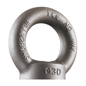
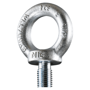
Lifting Eye Pewag PLGW-SN

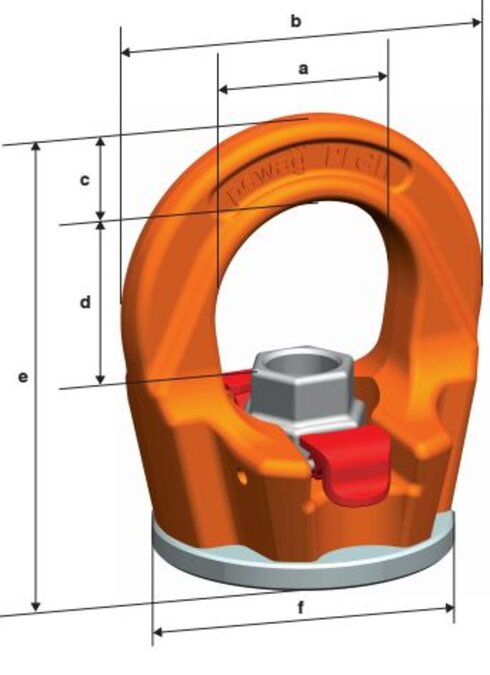
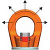
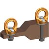
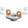
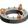
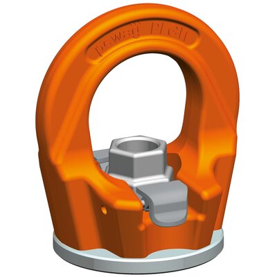
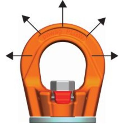
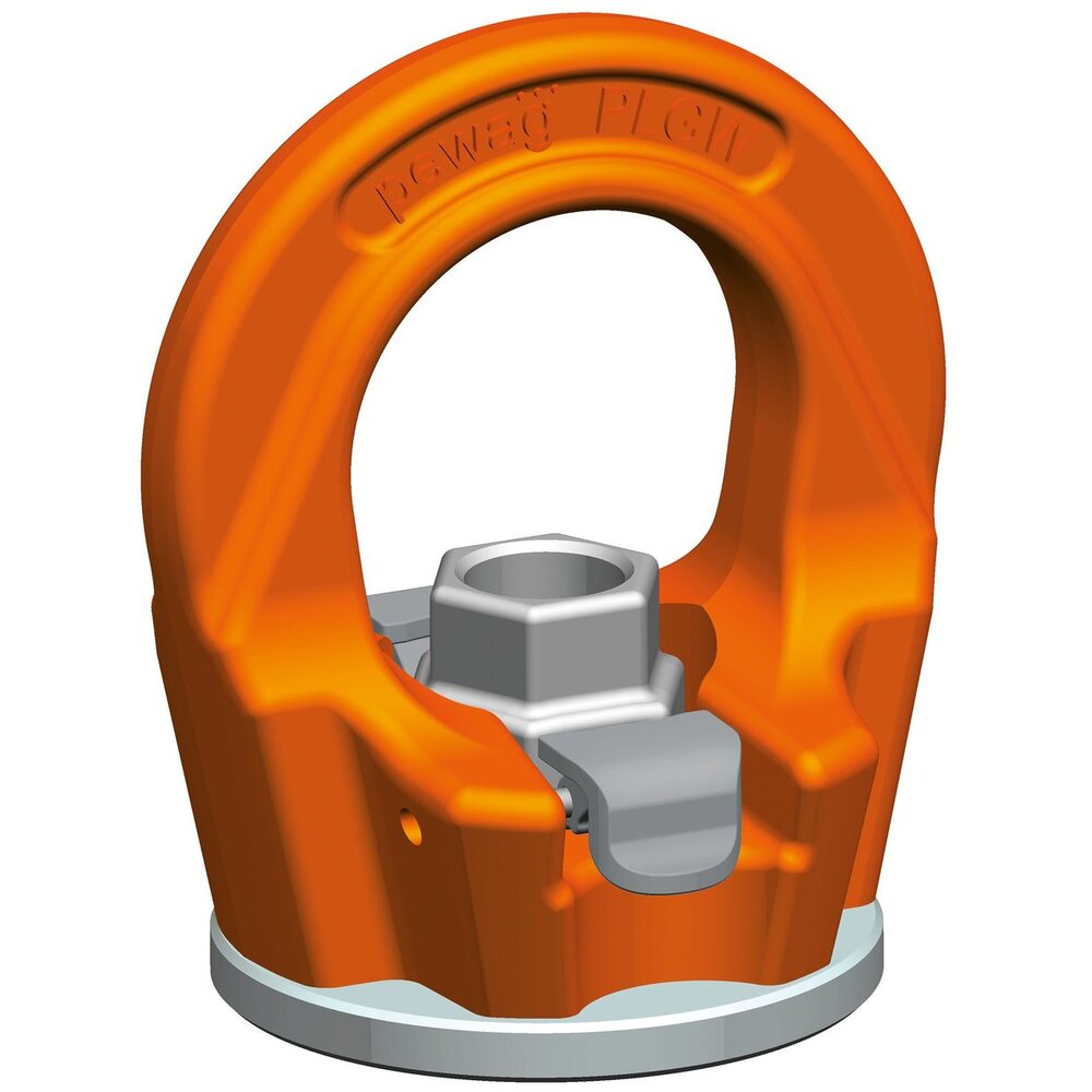
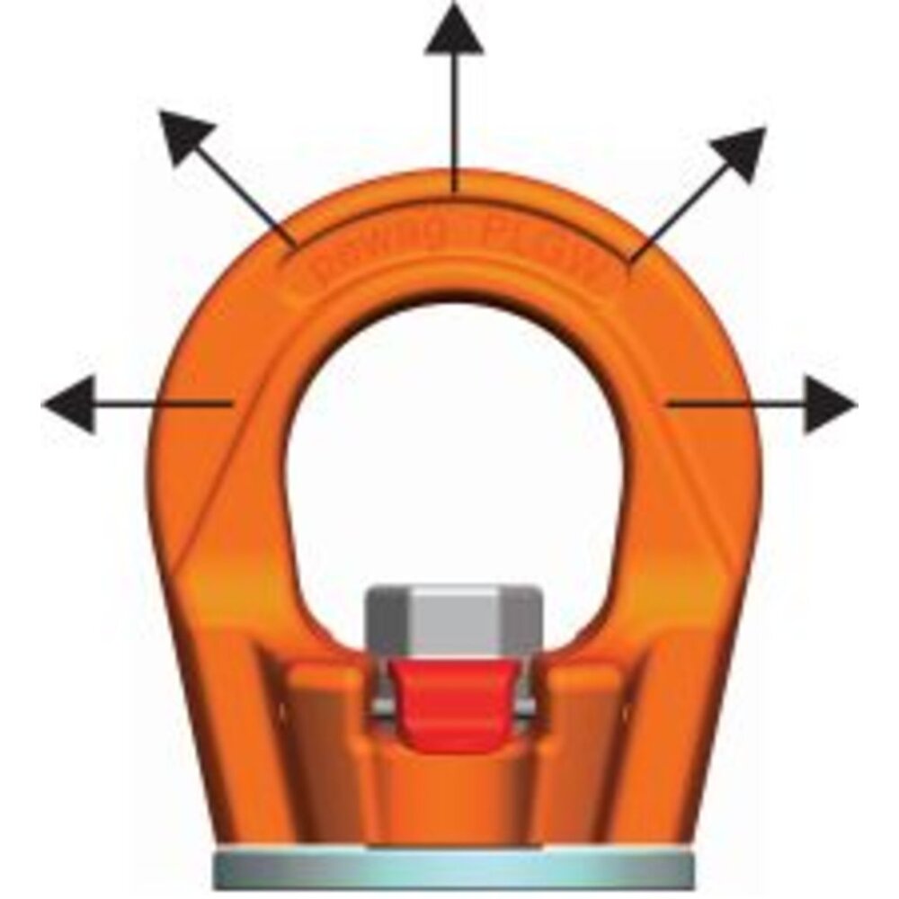
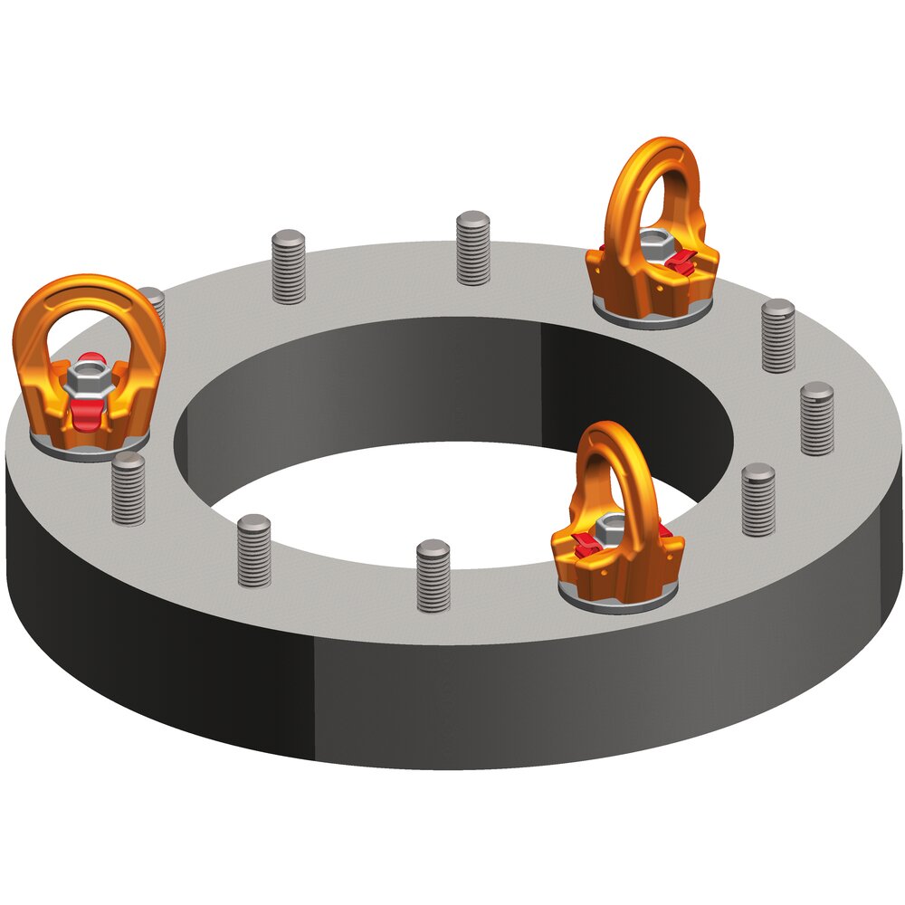
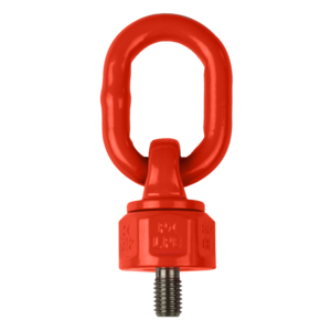
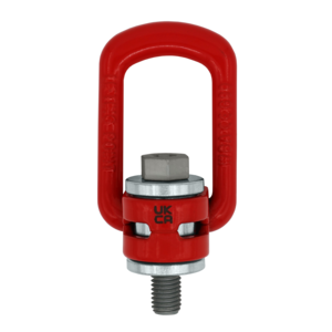
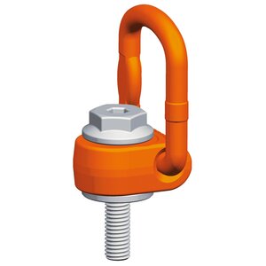
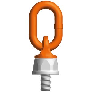
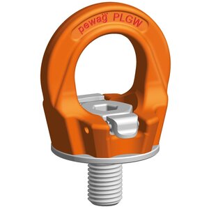
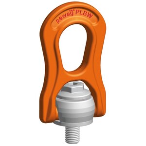
A revolutionary lifting eye which, thanks to the patented system with the red latches (see images) can be mounted by hand (latches in the upright position) and then freely rotate 360° around its own axis after installation (latches in the down position). The eye can be loaded within a range of 180/p>

Show more

Product number:

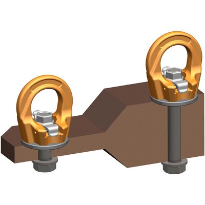
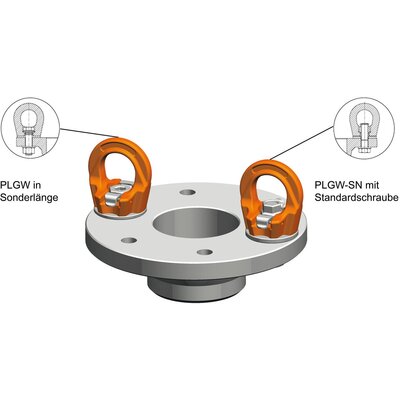
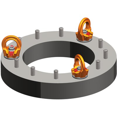
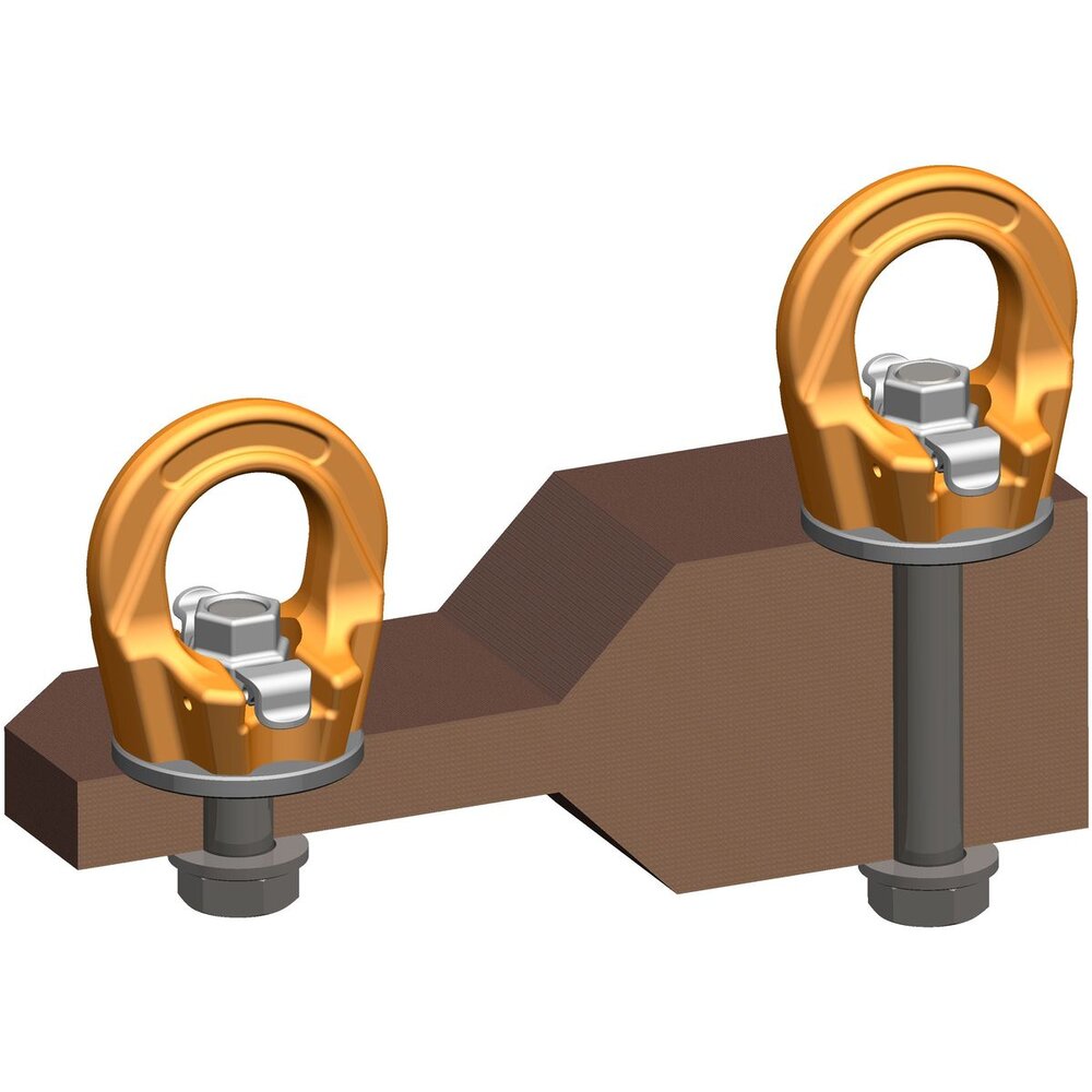
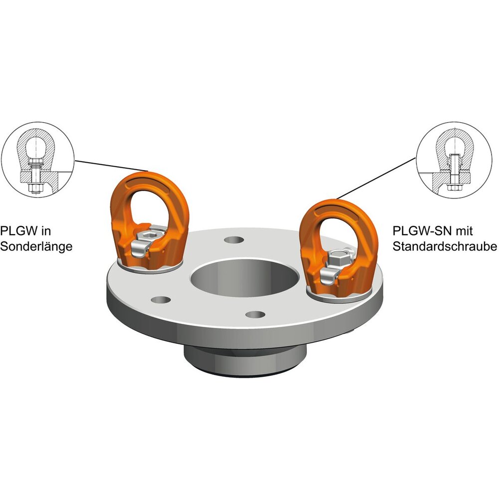
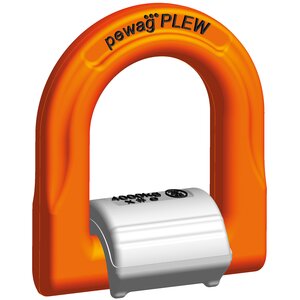
A revolutionary lifting eye which, thanks to the patented system with the red latches (see images) can be mounted by hand (latches in the upright position) and then freely rotate 360° around its own axis after installation (latches in the down position). The eye can be loaded within a range of 180°. The eye can be used individually or in combination with multiple eyes and should be tightened only by hand. This version of PLGW is used in those areas where a threaded bolt on the load is used instead of a simple thread. there is also the possibility to mount the lifting point PLGW-SN with a commercially available (standard) screw through the clearance hole. The benefit with the eye nut is that no matter the width of the load, the same lifting points ca be used. All you need are standard screws with different screw lenghts.

  • Material: Alloy steel
  • Marking: According to standard, CE-marked, WLL, and an individual serial number.
  • Finish: Painted.
  • Standard: EN 1677-1
    except grade/WLL
  • Safety factor: 4:1
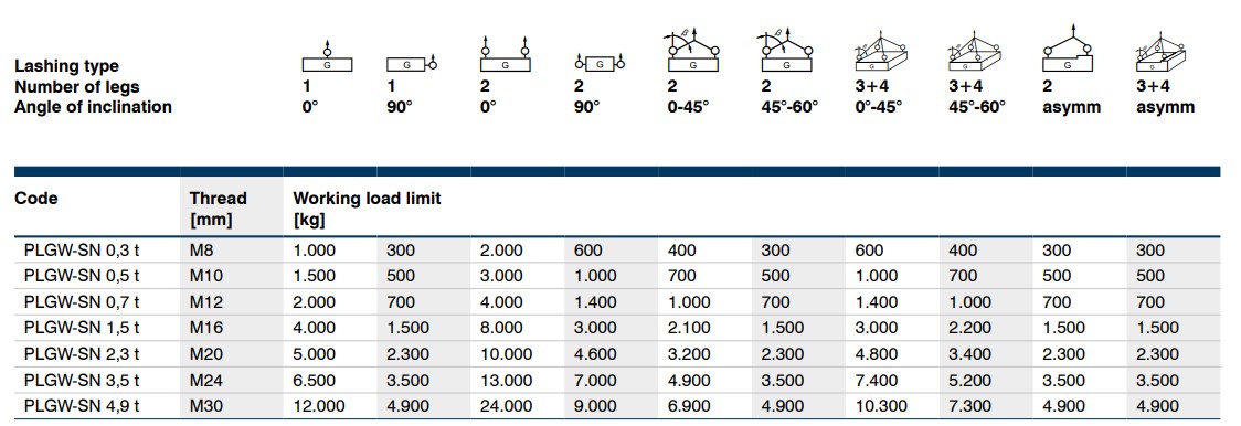
Load diagram

Method of lifting

drawing load capacities table 1

drawing load capacities table 2

drawing load capacities table 3

drawing load capacities table 4

drawing load capacities table 5

drawing load capacities table 6

drawing load capacities table 7

drawing load capacities table 8

drawing load capacities table 9

drawing load capacities table 10

Hexagon
 
 
Number of legs
1
1
2
2
2
2
3+4
3+4
2
3+4
 
 
Angle of inclination
90°
90°
0°-45°
45°-60°
0°-45°
45°-60°
asymm.
asymm.
 
Code
Thread
Load capacity tons
mm


PLGW-SN 0,3 t
M8
1,0
0,3
2,0
0,6
0,4
0,3
0,6
0,4
0,3
0,3
12
PLGW-SN 0,5 t
M10
1,5
0,5
3,0
1
0,7
0,5
1
0,7
0,5
0,5
12
PLGW-SN 0,7 t
M12
2
0,7
4
1,4
1
0,7
1,4
1
0,7
0,7
14
PLGW-SN 1,5 t
M16
4
1,5
8
3
2,1
1,5
3
2,2
1,5
1,5
19
PLGW-SN 2,3 t
M20
5
2,3
10
4,6
3,2
2,3
4,8
3,4
2,3
2,3
22
PLGW-SN 3,5 t
M24
6,5
3,5
13
7
4,9
3,5
7,4
5,2
3,5
3,5
27
PLGW-SN 4,9 t*
M30
12
4,9
24
9
6,9
4,9
10,3
7,3
4,9
4,9
36