Wire Rope Diameter
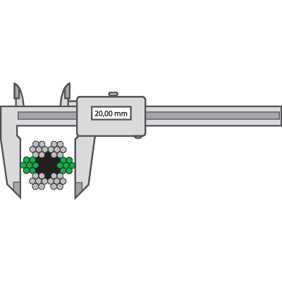
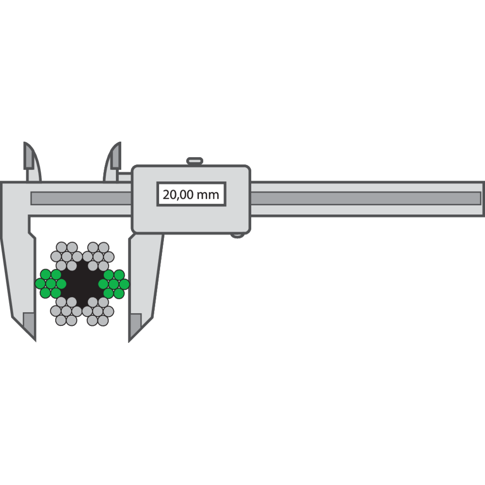
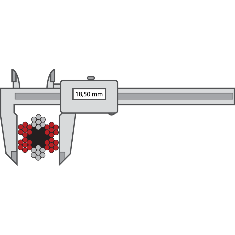
The rope diameter should always be checked before installation. Measure a straight part of the rope. Two parts with minimum distance of one meter should be measured. At every point two measurements should be done, with an angle of 90 degrees displacement in relation to each other. The average between the two measurements should be according to the tolerance detailed in the tables below.
Steel wire ropes for general applications
| Nominal rope Ø | Tolerance of nominal diameter on unloaded rope | |
|---|---|---|
| mm | % | |
| 2 - <4 | 0 +8 | |
| 4 - <6 | 0 +7 | |
| 6 - <8 | 0 +6 | |
| =8 | 0 +5 | |
| Nominal rope Ø | The difference between two measurements expressed as the percent from nominal diameter for unloaded rope | |
|---|---|---|
| Rope with strands that are exclusively of wire | Ropes with strands that incorporate fibre centres | |
| mm | max % | max % |
| 2 - <4 | +7 | - |
| 4 - <6 | +6 | +8 |
| 6 - <8 | +5 | +7 |
| 8 ja suurempi | +4 | +6 |
Steel wire ropes for person elevators
| Nominal rope Ø | Tolerance for nominal diameter for ropes with fibre core/synthetic core | Tolerance for nominal diameter ropes with steel core | ||||
|---|---|---|---|---|---|---|
| Unloaded | Loaded to 5% of min breaking load | Loaded to 10% of min breaking load | Unloaded | Loaded to 5% of min breaking load | Loaded to 10% of min breaking load | |
| mm | max % | min % | min % | max % | min % | max % |
| < 10 | +6 | +1 | 0 | +3 | 0 | -1 |
| > 10 | +5 | +1 | 0 | +2 | 0 | -1 |
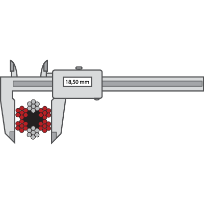


| Nominal rope Ø | Difference between two measurements expressed as percentage of nominal diameter under a load equivalent to 5% or 10% of min breaking load | |
|---|---|---|
| mm | Rope ovality max % |
Average diameter variation max % |
| <8 | +4 | +3 |
| =8 | +3 | +2 |
Instruction for Handling of Steel Wire Rope
Following instructions and warnings are issued to give guidelines for safe installation and handle. Warning texts point at areas where large risk for considerable reduction of life of the steel wire rope and/or damage on equipment and to person by wrong handle exists.
WARNING! Handle and installation of steel wire ropes shall always be performed by a person with knowledge and education about valid safety regulations.
Packing
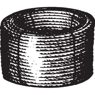
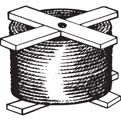
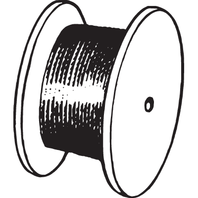
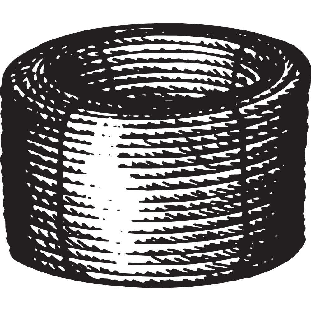
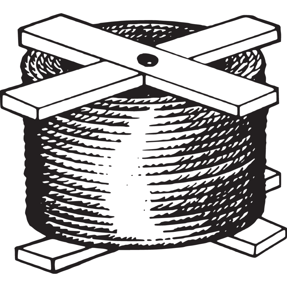
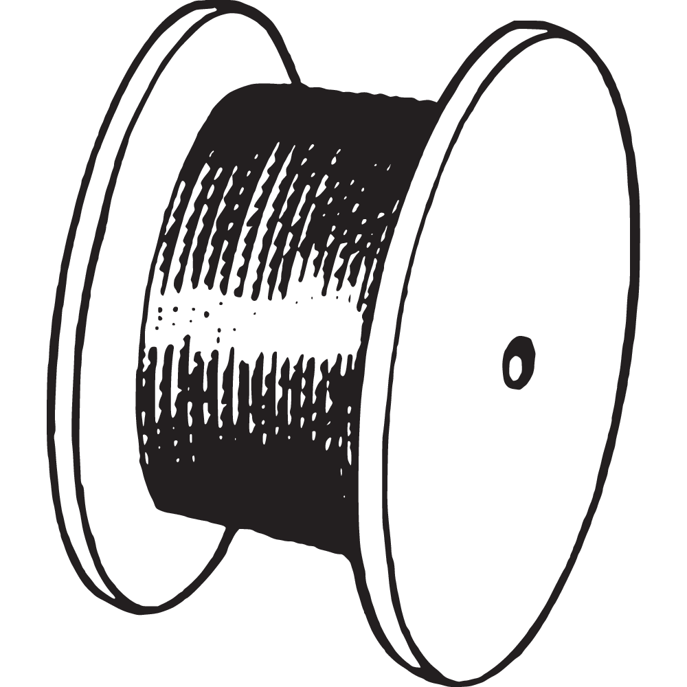
Wire rope is generally delivered in a coil, plywood or wooden reel. On the European mainland a cross reel is also common. Please specify packaging when ordering.



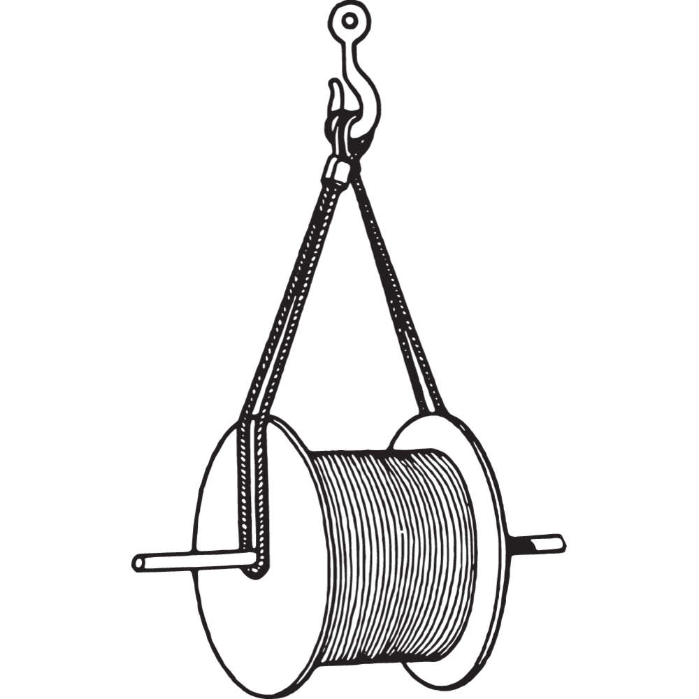
Lifting and Handling
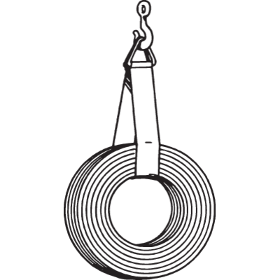
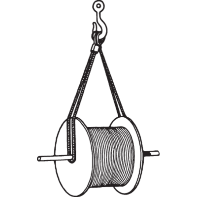
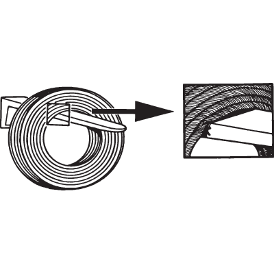
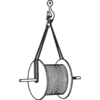
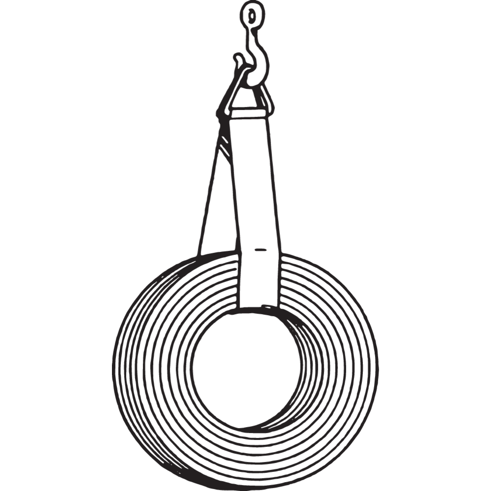
Ensure that the rope is not damaged by fork lifts or other handling equipment, by lifting or handling.
WARNING! Wrong handling/lifting can damage the rope.


Storage
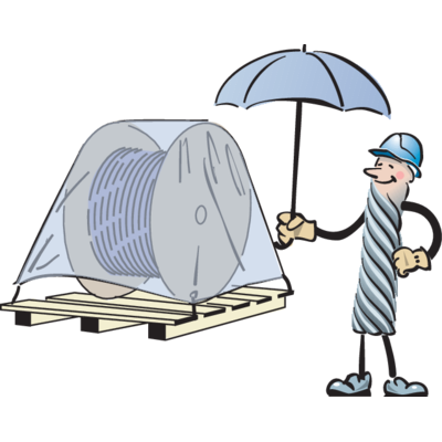
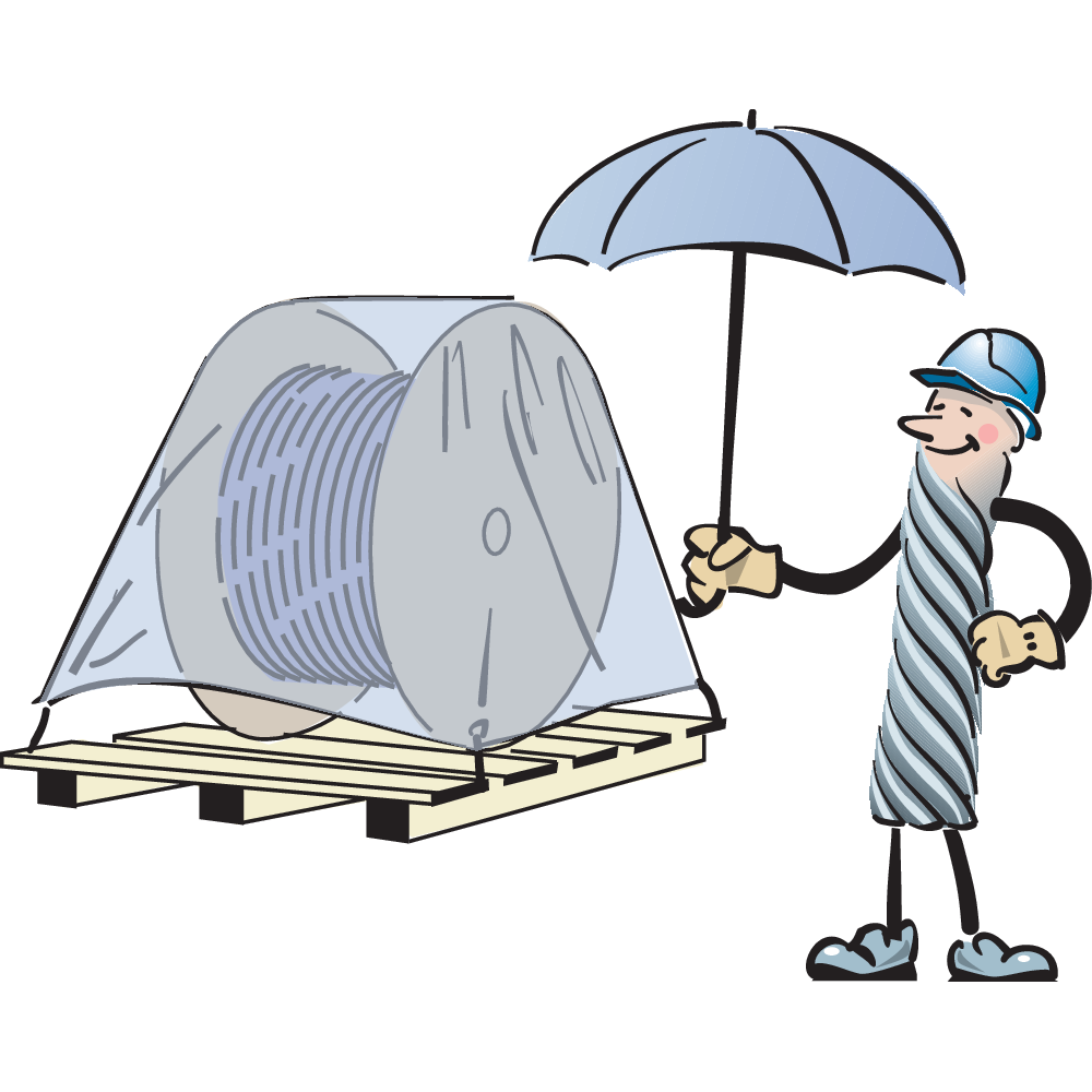
Steel wire ropes shall be stored in a dry and well ventilated location. Cover with waterproof material by outside storage. Rotate the reel periodically during long periods of storage, partuculary in warm environments. The ropes shall be examined regulary and lubricated if necessary.
WARNING! Incorrect storing can cause damage on the wire rope. Never store the rope in environment with highly various temperature.

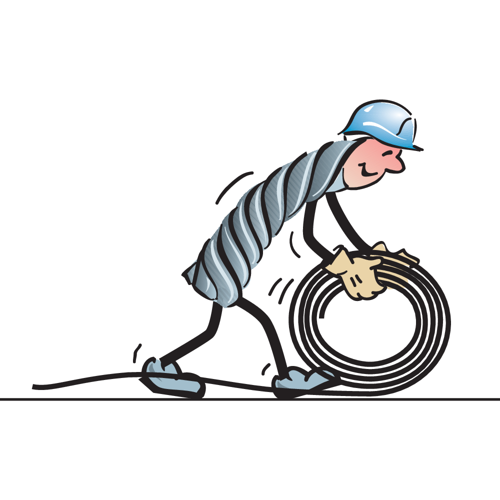
Unwinding
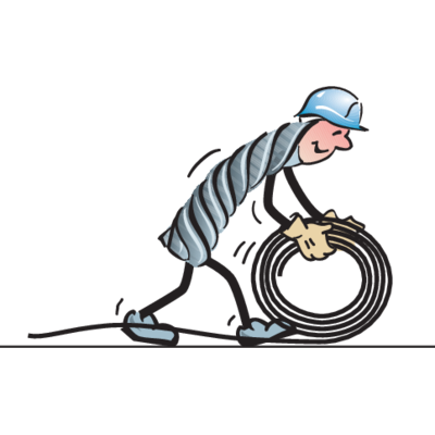
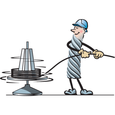
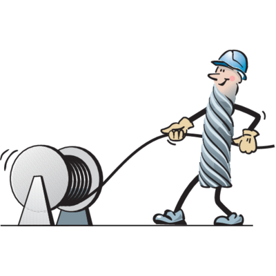
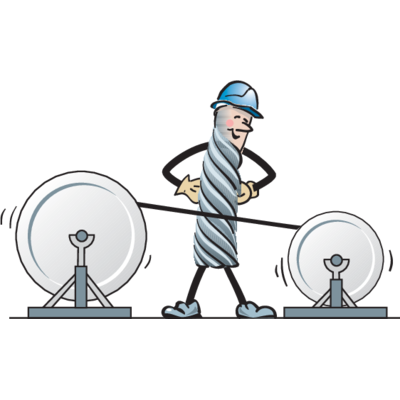
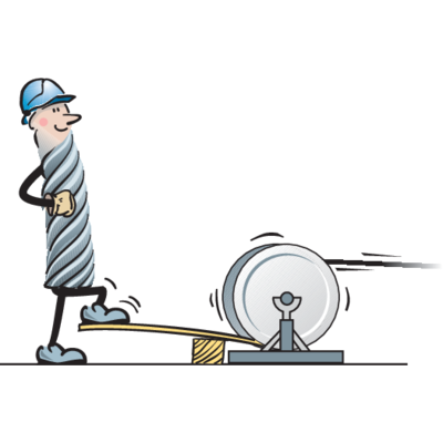
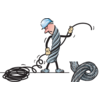
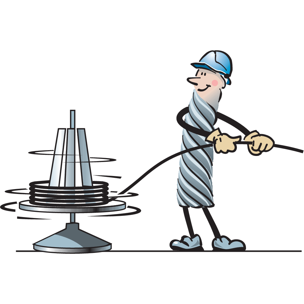
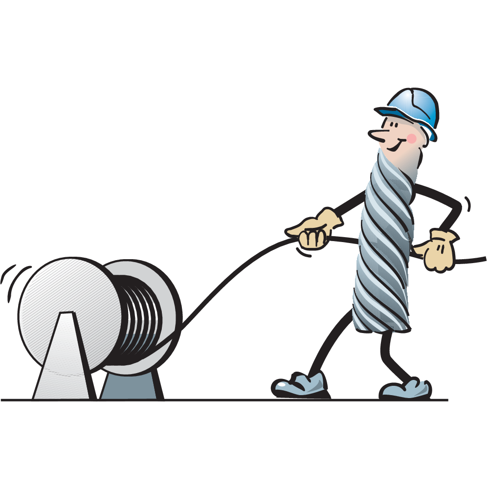
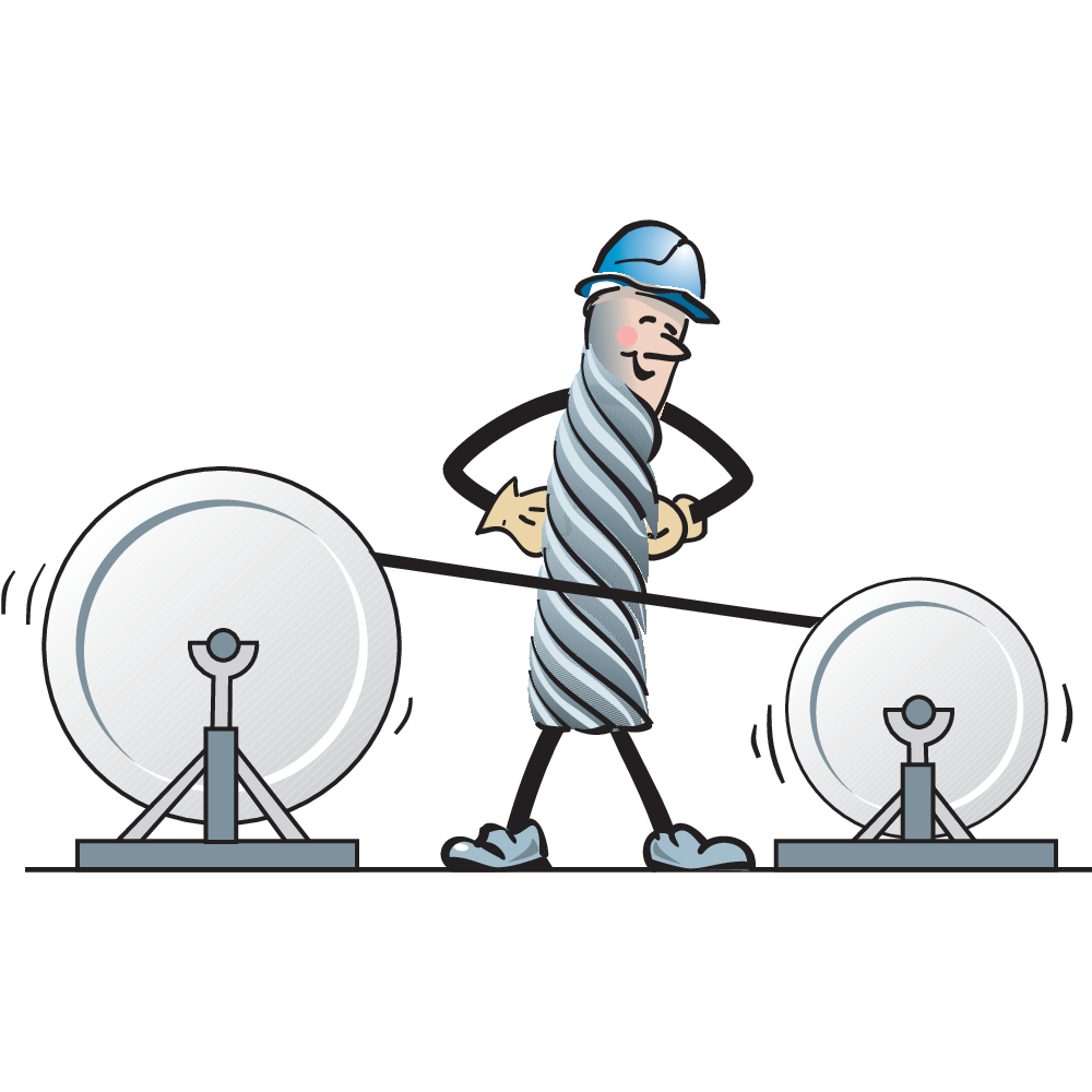
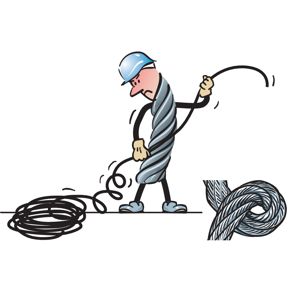
Wrong coiling can cause serious damage to the steel wire rope. Coil or wind according to the following:
- Reels should be rolled out or alternatively placed on a turnable centre.
- Cross reels and drums should be placed on a shaft that allows it to rotate.
- Wind and unwind the rope in the same direction.
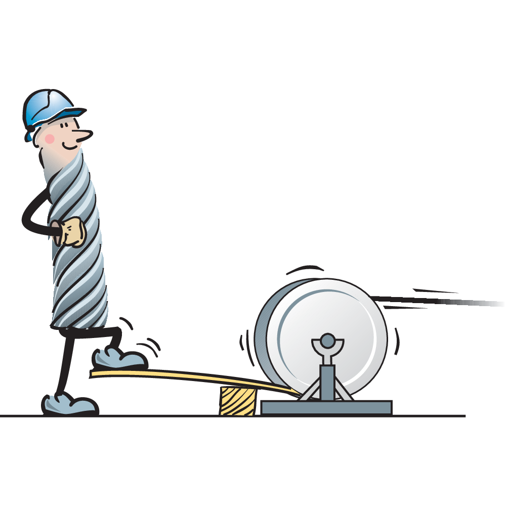
- In some cases it may be necessary to brake the drum.
WARNING! Wrong "opening" of packing can cause serious injury to personnel, first ensure that the rope is under control.
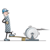
Never pull a rope from a stationary reel or drum - due to the risk of kinking.
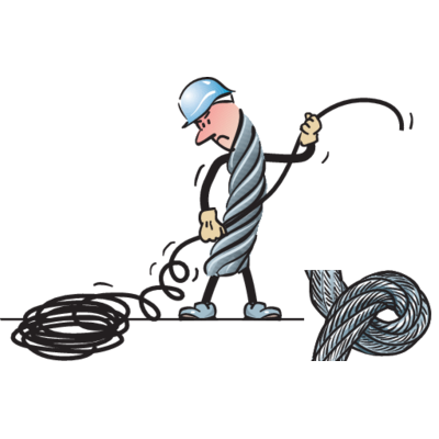
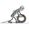

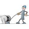
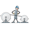


Cutting
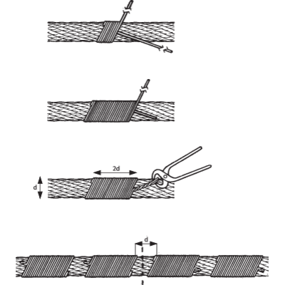
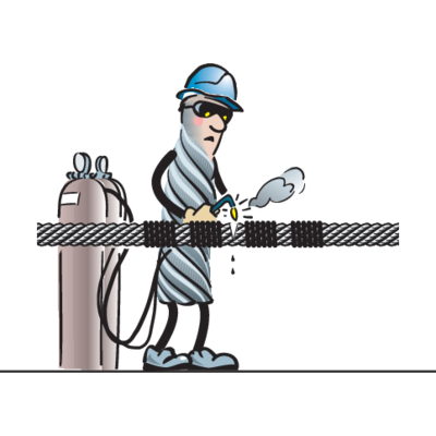
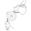
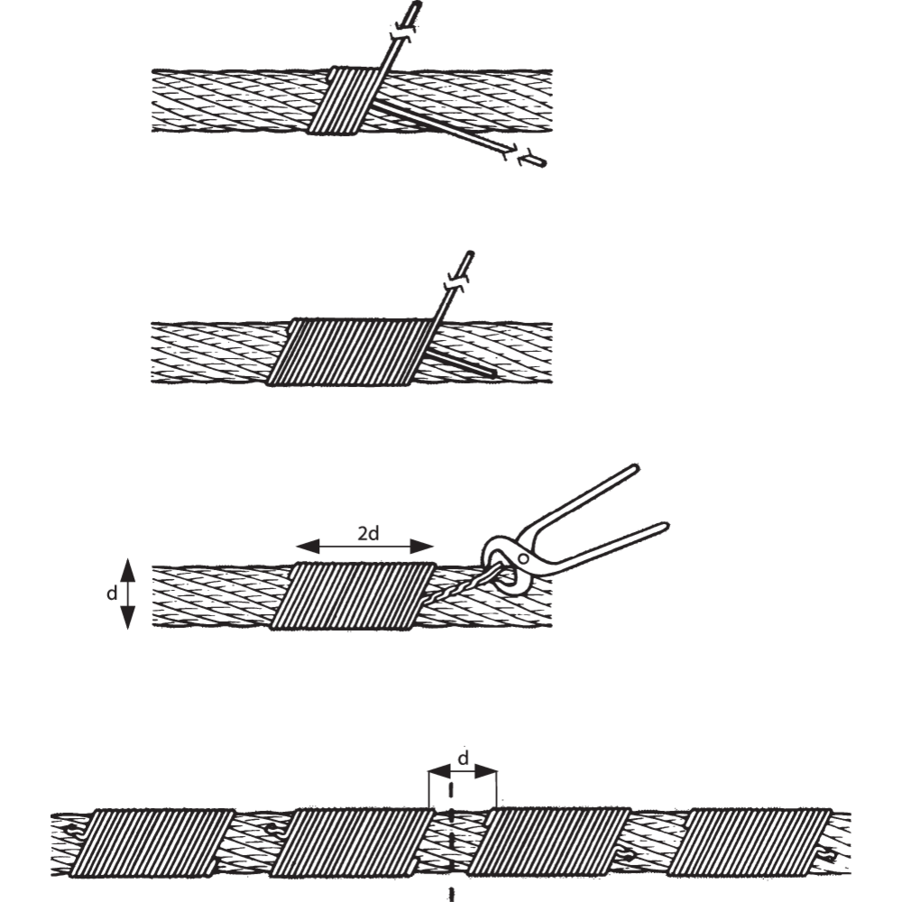
Usually ropes are supplied in cut lengths, with "tapered" ends made by annealing. If the rope is required to be cut during assembly the rope shall be seized each side of the cut, to prevent damage from opening strands and/or changing lay length.
One seizing either side of the cut is normally sufficient for preformed ropes. For "rotation resistant" and special wire ropes a minimum of two seizings each side of the cut will be necessary. The length of each seizing should be a minimum 2 x rope diameter.
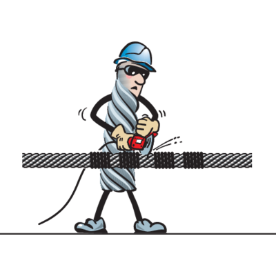
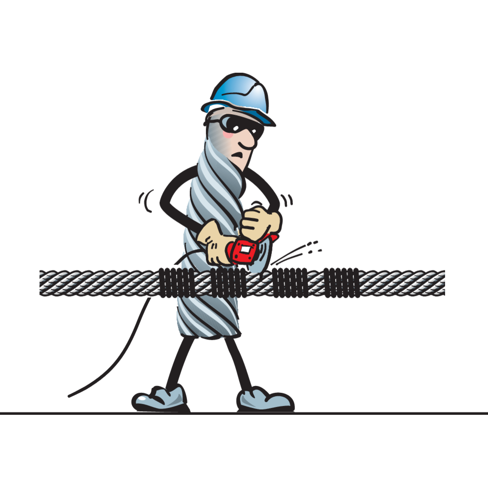
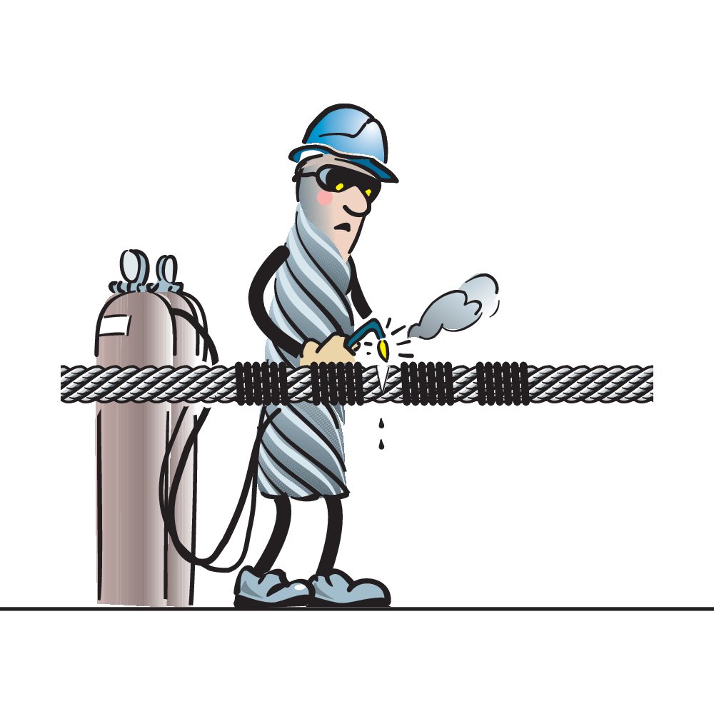
Cutting should be made with a high speed abrasive disc cutter, cutting torch or other suitable mechanical or hydraulic shearing equipment.
After the rope has been cut the seizing should be left until all the wires are welded or otherwise secured.
WARNING! Incorrect cutting can cause damage to the rope. Be extra careful when cutting rotation resistant ropes.
Use safety goggles and other appropriate safety equipment when using a disc cutter or other mechanical or electrical devices.



Drum - Groove
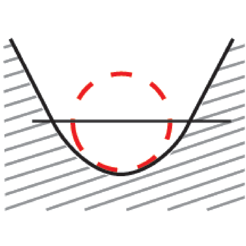
Check the general condition of the drum. If the drum is grooved, check the radius and pitch considered the diameter of the new rope.
WARNING! The drum can in some cases cause damages on the rope and with that too early discard. Too small diameter on the drum can give permanent distortions on the rope which definitely result in too early discard.
![drum [new2]_225mm_2](/sites/certex-fi/techdoc_import/Technical%20information%20general/STEEL%20WIRE%20ROPE%20PRODUCTS/OLD_Technical%20information/Steel%20wire%20rope/Handling%20and%20installation/10488/image-thumb__10488__general-base/drum-new2-_225mm_2.2785619b.png)
![drum [new2]_225mm_2](/sites/certex-fi/techdoc_import/Technical%20information%20general/STEEL%20WIRE%20ROPE%20PRODUCTS/OLD_Technical%20information/Steel%20wire%20rope/Handling%20and%20installation/10488/image-thumb__10488__general-thumb/drum-new2-_225mm_2.ce941ef7.png)
![drum [new2]_225mm_2](/sites/certex-fi/techdoc_import/Technical%20information%20general/STEEL%20WIRE%20ROPE%20PRODUCTS/OLD_Technical%20information/Steel%20wire%20rope/Handling%20and%20installation/10488/image-thumb__10488__general-base/drum-new2-_225mm_2.2785619b.png)
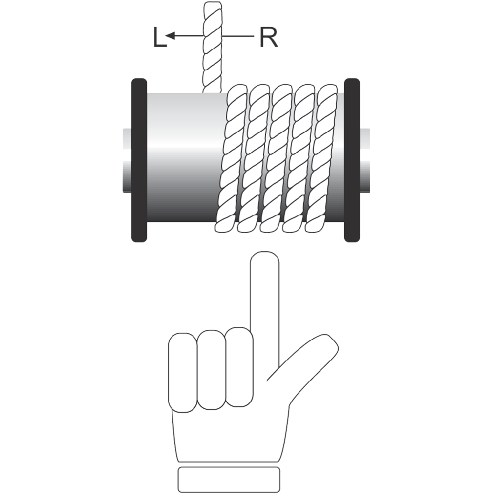
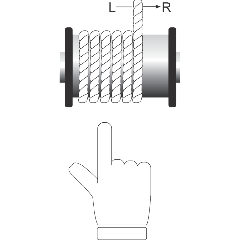
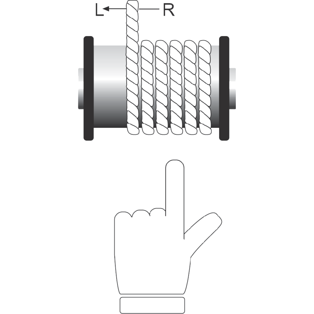
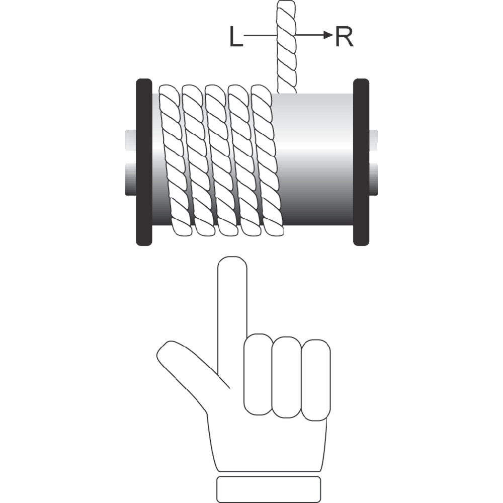
Drum - Correct Coiling
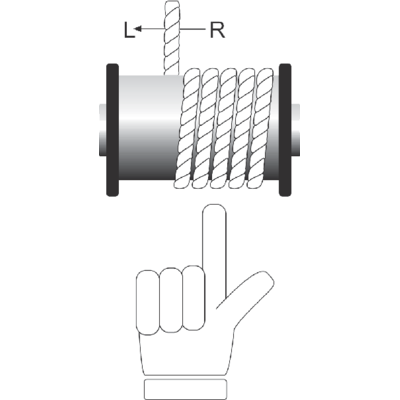
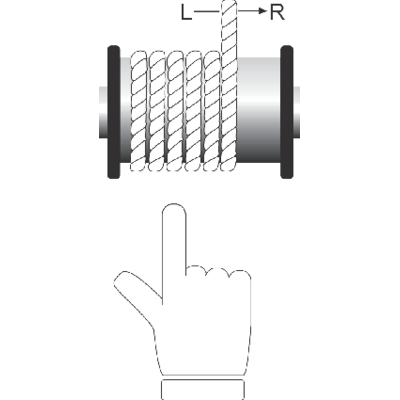
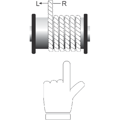
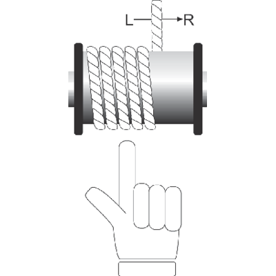
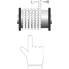
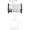
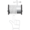
The rotation direction and the attachment point of the rope determines whether right or left hand lay rope should be used. To determine the correct rope the following rule should be followed:
Right thread groove on the drum - left hand lay rope.
Left thread groove on the drum - right hand lay rope.
WARNING! Incorrect choice of lay can adversely affect rope performance.
Pass a shaft through the reel and place the reel in a suitable stand which allows it to rotate and be braked to avoid over run during installation. Where multi-layer coiling is involved it may be necessary for the reel to be placed in equipment which has the capability of providing a back tension to the rope as it is being transferred from reel to drum. This is to ensure that the underlaying (and subsequent) laps are wound tightly on the drum.
WARNING! Incorrect coiling may cause severe damage to the wire rope as well as its performance.


Drum - Connection
When installing the new rope a pulling grip alternatively an eye can be used as connection between old and new rope.
Individual turn between two ropes when installing can be possibel with a swivel, which avoid turn being transmitted from the "old" rope into the new rope.
WARNING! Always check that "rope tension" not exist during installation. Stocking or connection should be equiped with swivel.
![eye-sock [Converted]_225mm_2](/sites/certex-fi/techdoc_import/Technical%20information%20general/STEEL%20WIRE%20ROPE%20PRODUCTS/OLD_Technical%20information/Steel%20wire%20rope/Handling%20and%20installation/10490/image-thumb__10490__general-base/eye-sock-converted-_225mm_2.b53a4296.png)
![eye-sock [Converted]_225mm_2](/sites/certex-fi/techdoc_import/Technical%20information%20general/STEEL%20WIRE%20ROPE%20PRODUCTS/OLD_Technical%20information/Steel%20wire%20rope/Handling%20and%20installation/10490/image-thumb__10490__general-thumb/eye-sock-converted-_225mm_2.b26b9b83.png)
![eye-sock [Converted]_225mm_2](/sites/certex-fi/techdoc_import/Technical%20information%20general/STEEL%20WIRE%20ROPE%20PRODUCTS/OLD_Technical%20information/Steel%20wire%20rope/Handling%20and%20installation/10490/image-thumb__10490__general-base/eye-sock-converted-_225mm_2.b53a4296.png)
Drum - Multiple Layers
Multiple layers of wire on the drum kan cause deformation (flattening, pressing etc) in the lower layers in not right rope construction is used and/or by wrong winding.
![multiple-layers-[Converted][new]_225mm_2](/sites/certex-fi/techdoc_import/Technical%20information%20general/STEEL%20WIRE%20ROPE%20PRODUCTS/OLD_Technical%20information/Steel%20wire%20rope/Handling%20and%20installation/10489/image-thumb__10489__general-base/multiple-layers--converted-new-_225mm_2.4c3c1997.png)
![multiple-layers-[Converted][new]_225mm_2](/sites/certex-fi/techdoc_import/Technical%20information%20general/STEEL%20WIRE%20ROPE%20PRODUCTS/OLD_Technical%20information/Steel%20wire%20rope/Handling%20and%20installation/10489/image-thumb__10489__general-thumb/multiple-layers--converted-new-_225mm_2.87f8124b.png)
![multiple-layers-[Converted][new]_225mm_2](/sites/certex-fi/techdoc_import/Technical%20information%20general/STEEL%20WIRE%20ROPE%20PRODUCTS/OLD_Technical%20information/Steel%20wire%20rope/Handling%20and%20installation/10489/image-thumb__10489__general-base/multiple-layers--converted-new-_225mm_2.4c3c1997.png)
Drum - Capacity
The following formula gives an approximate indication regarding length of rope of a given diameter (d) which can be installed onto a drum.
Rope length (m) = (A+B) x A x C x p x 106 / d2
A, B and C are quoted in metres and d in millimetres.
Note that ropes are normally manufactured to a maximum oversized tolerance.
![drum-capacity[new]_225mm_2](/sites/certex-fi/techdoc_import/Technical%20information%20general/STEEL%20WIRE%20ROPE%20PRODUCTS/OLD_Technical%20information/Steel%20wire%20rope/Handling%20and%20installation/10491/image-thumb__10491__general-base/drum-capacity-new-_225mm_2.3fd31107.png)
![drum-capacity[new]_225mm_2](/sites/certex-fi/techdoc_import/Technical%20information%20general/STEEL%20WIRE%20ROPE%20PRODUCTS/OLD_Technical%20information/Steel%20wire%20rope/Handling%20and%20installation/10491/image-thumb__10491__general-thumb/drum-capacity-new-_225mm_2.62c0945e.png)
![drum-capacity[new]_225mm_2](/sites/certex-fi/techdoc_import/Technical%20information%20general/STEEL%20WIRE%20ROPE%20PRODUCTS/OLD_Technical%20information/Steel%20wire%20rope/Handling%20and%20installation/10491/image-thumb__10491__general-base/drum-capacity-new-_225mm_2.3fd31107.png)
Drum - Fleet Angle
Too large a fleet angle can cause excessive wear of the rope against the adjacent wrap on the drum. This can also lead to torsional problems.
![fleetangle[new]._225mm_2](/sites/certex-fi/techdoc_import/Technical%20information%20general/STEEL%20WIRE%20ROPE%20PRODUCTS/Steel%20wire%20rope/Steel%20wire%20rope%20-%20handling%20and%20installation/10456/image-thumb__10456__general-base/seil_5.f92ce9c7.png)
![fleetangle[new]._225mm_2](/sites/certex-fi/techdoc_import/Technical%20information%20general/STEEL%20WIRE%20ROPE%20PRODUCTS/Steel%20wire%20rope/Steel%20wire%20rope%20-%20handling%20and%20installation/10456/image-thumb__10456__general-thumb/seil_5.a5cb8c72.png)
![fleetangle[new]._225mm_2](/sites/certex-fi/techdoc_import/Technical%20information%20general/STEEL%20WIRE%20ROPE%20PRODUCTS/Steel%20wire%20rope/Steel%20wire%20rope%20-%20handling%20and%20installation/10456/image-thumb__10456__general-base/seil_5.f92ce9c7.png)
"Breaking in"
After the rope has been installed and before it is taken into operation, several run-throughs of normal operation circle should be carried out under light load to let the rope adjust itself to the actual operating conditions.
![feather-weight[new]_225mm_2](/sites/certex-fi/techdoc_import/Technical%20information%20general/STEEL%20WIRE%20ROPE%20PRODUCTS/OLD_Technical%20information/Steel%20wire%20rope/Handling%20and%20installation/10492/image-thumb__10492__general-base/feather-weight-new-_225mm_2.996762c8.png)
![feather-weight[new]_225mm_2](/sites/certex-fi/techdoc_import/Technical%20information%20general/STEEL%20WIRE%20ROPE%20PRODUCTS/OLD_Technical%20information/Steel%20wire%20rope/Handling%20and%20installation/10492/image-thumb__10492__general-thumb/feather-weight-new-_225mm_2.3f61246f.png)
![feather-weight[new]_225mm_2](/sites/certex-fi/techdoc_import/Technical%20information%20general/STEEL%20WIRE%20ROPE%20PRODUCTS/OLD_Technical%20information/Steel%20wire%20rope/Handling%20and%20installation/10492/image-thumb__10492__general-base/feather-weight-new-_225mm_2.996762c8.png)
Rope discard
Discard the wire rope in accordance with current regulations or according to the manufacturers recommendations.
Only a qualified and experienced person should be responsible for discard.
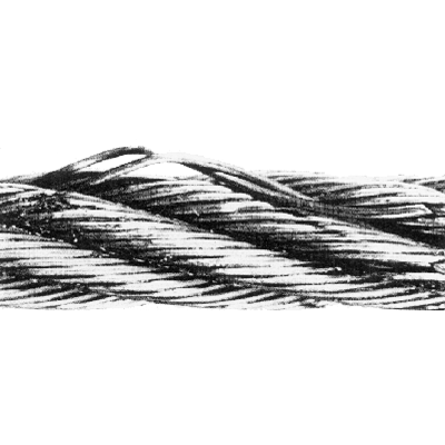
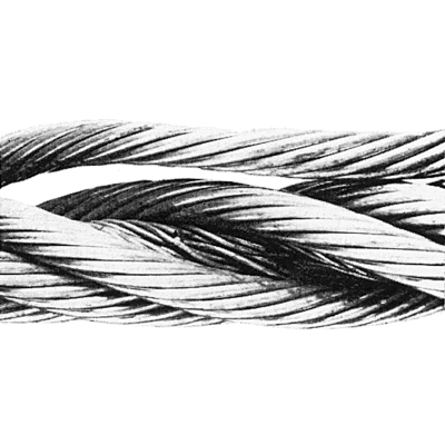
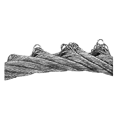
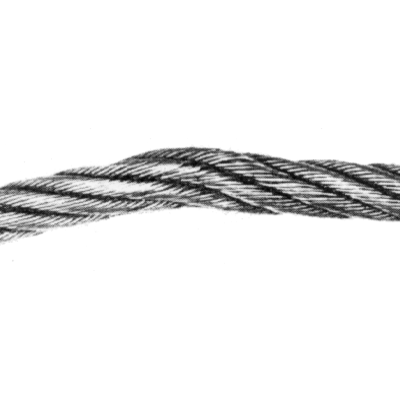
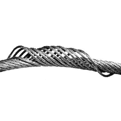
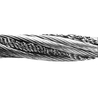
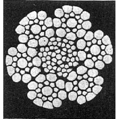
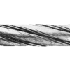
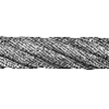
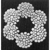
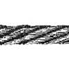
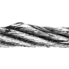
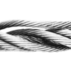
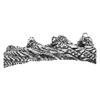
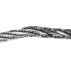
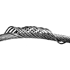
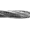
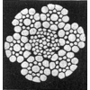
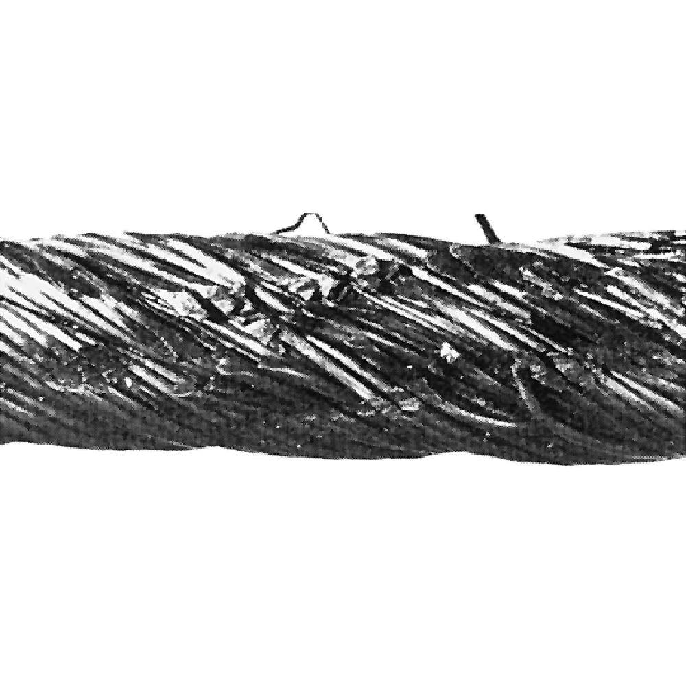
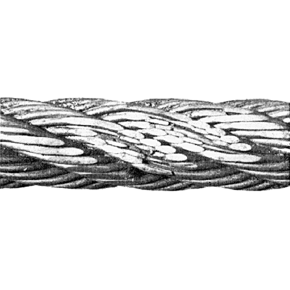
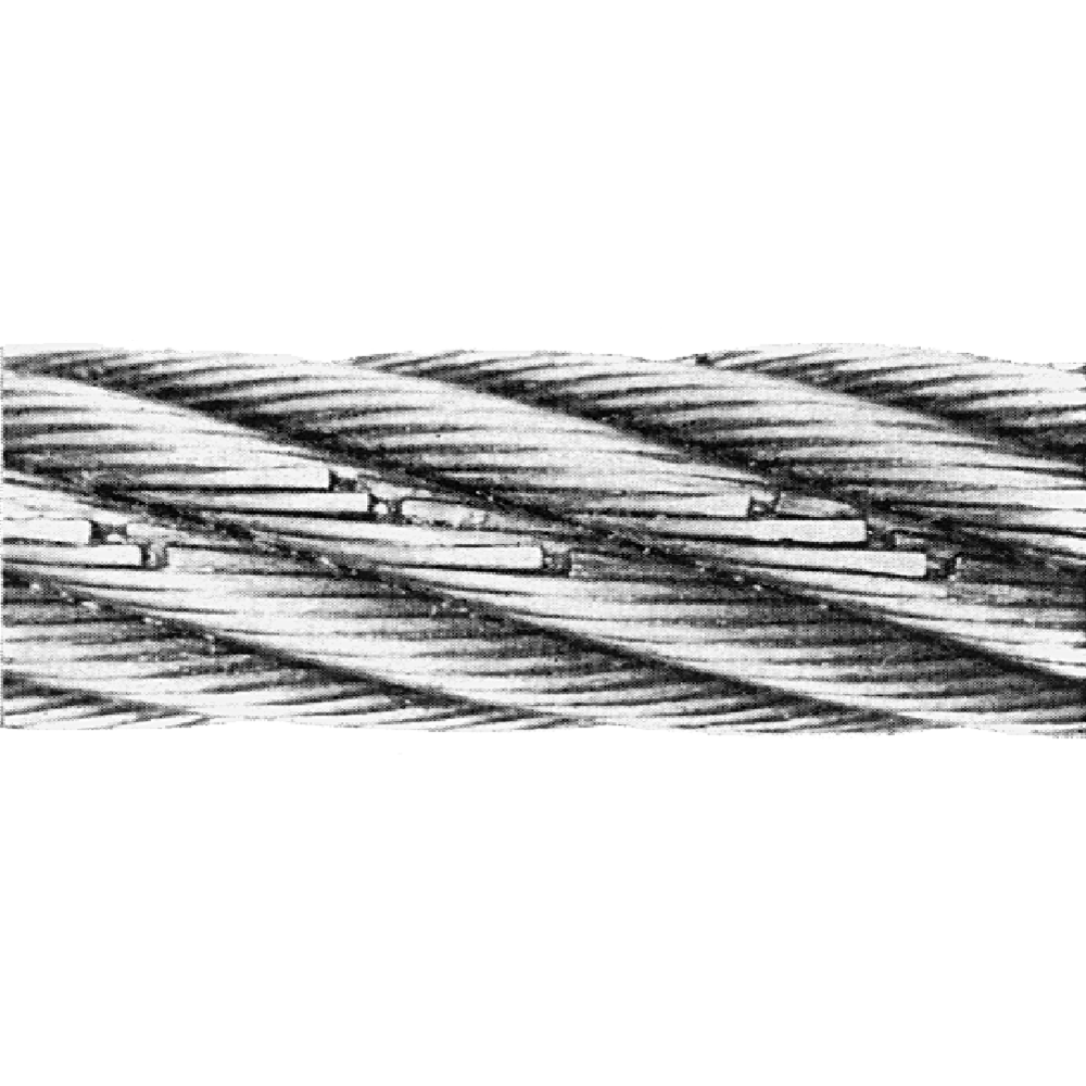
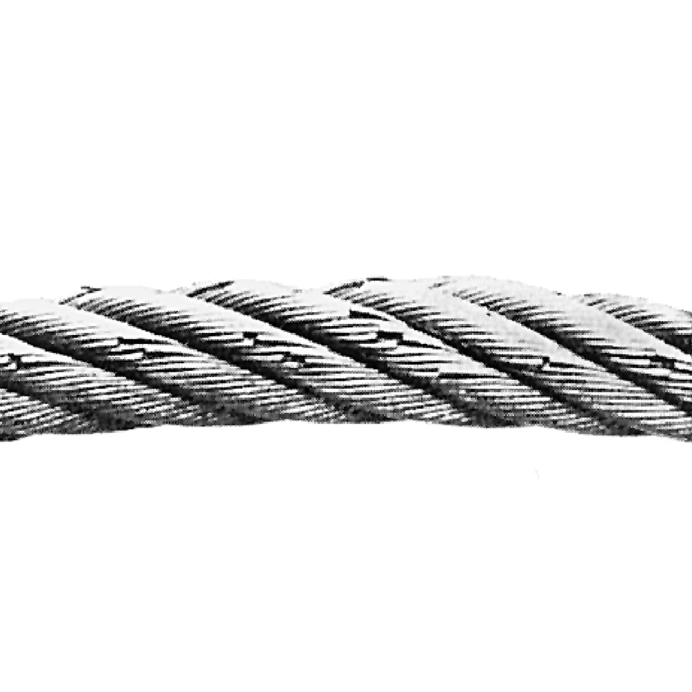
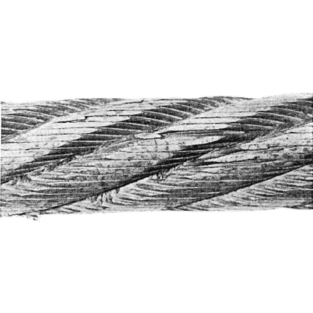
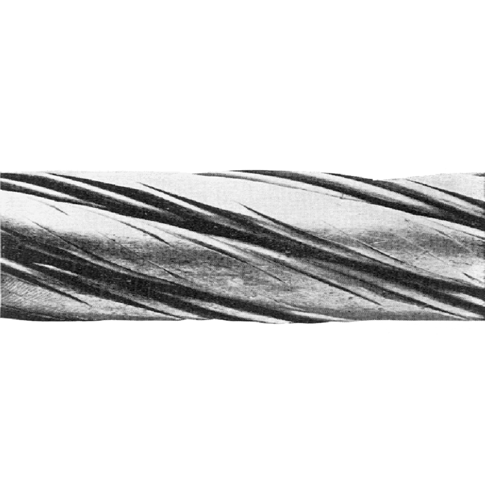
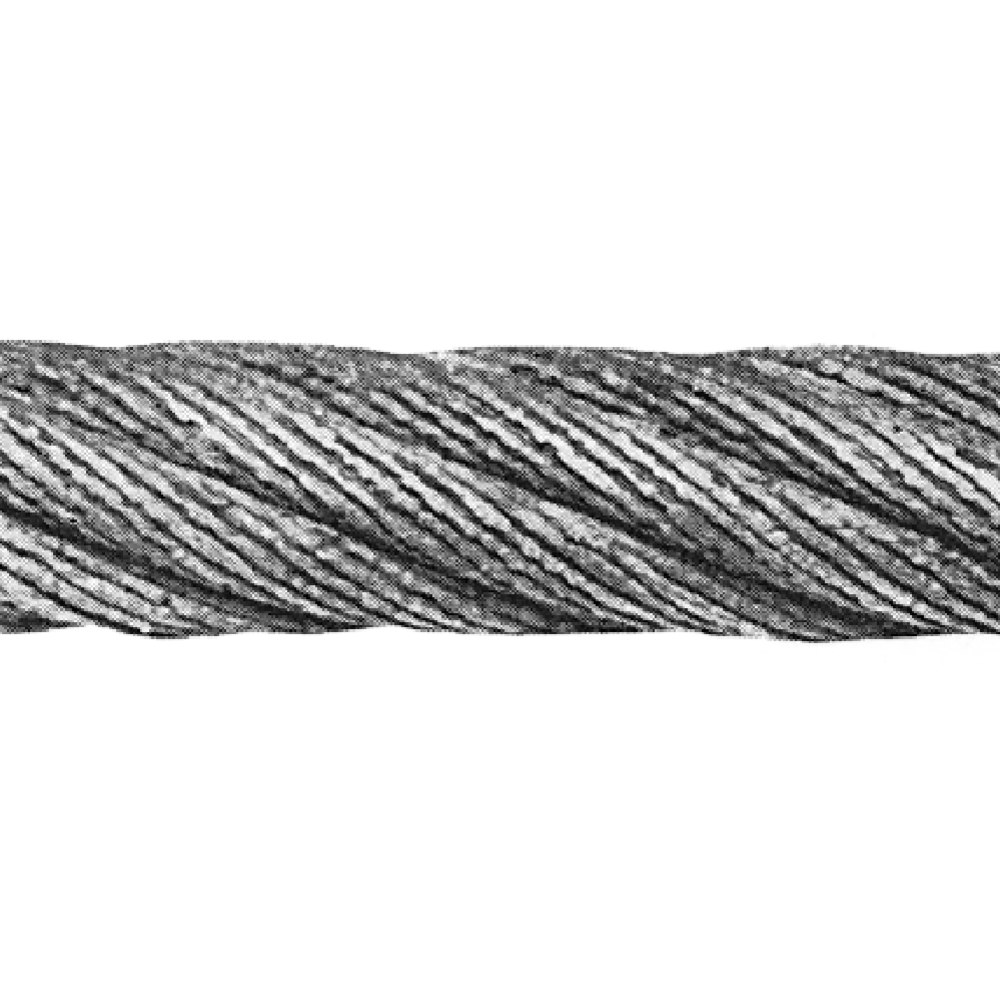
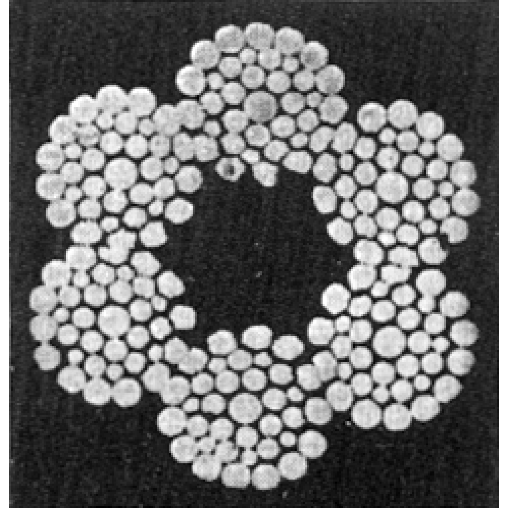
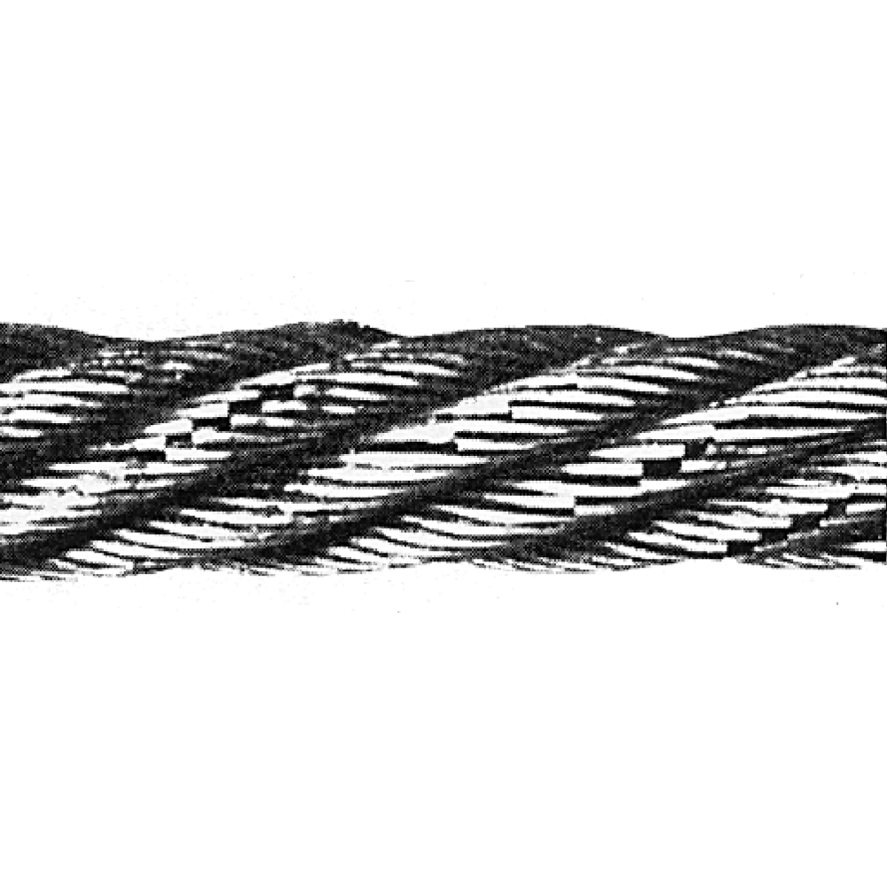
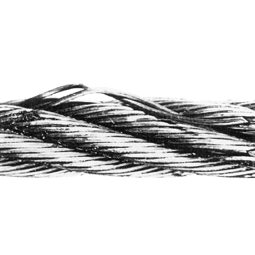
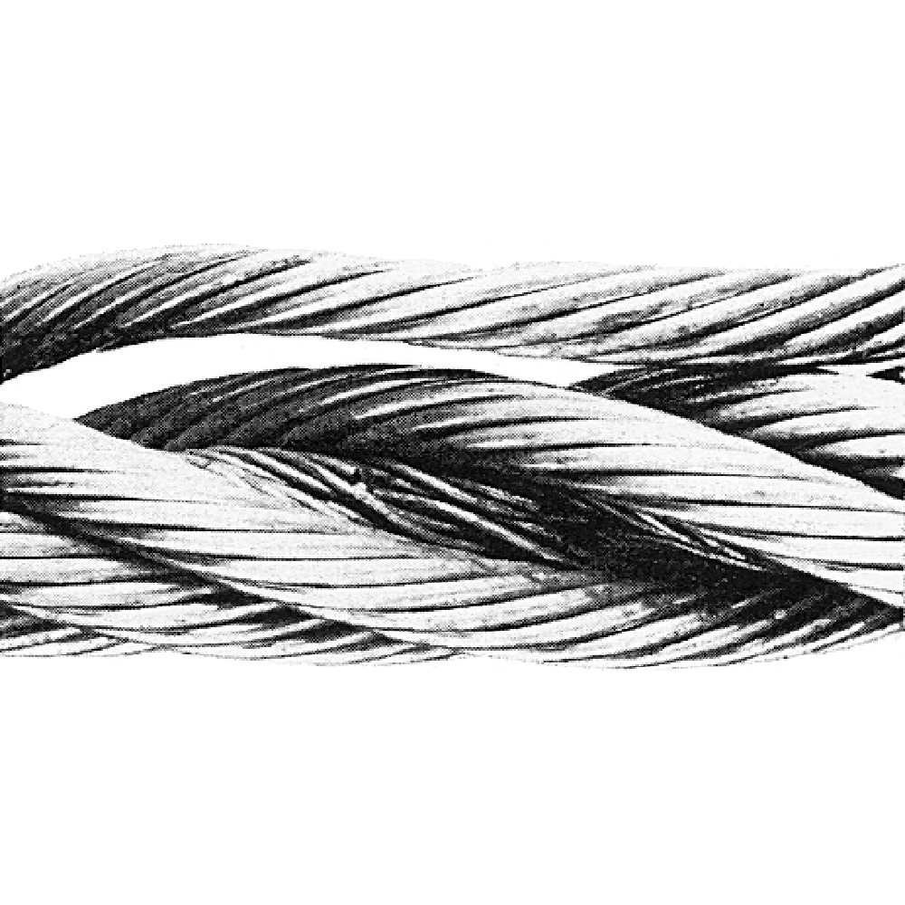
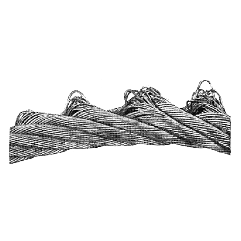
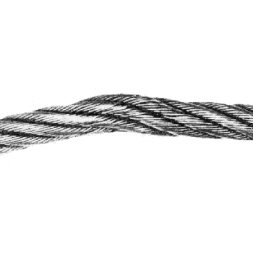
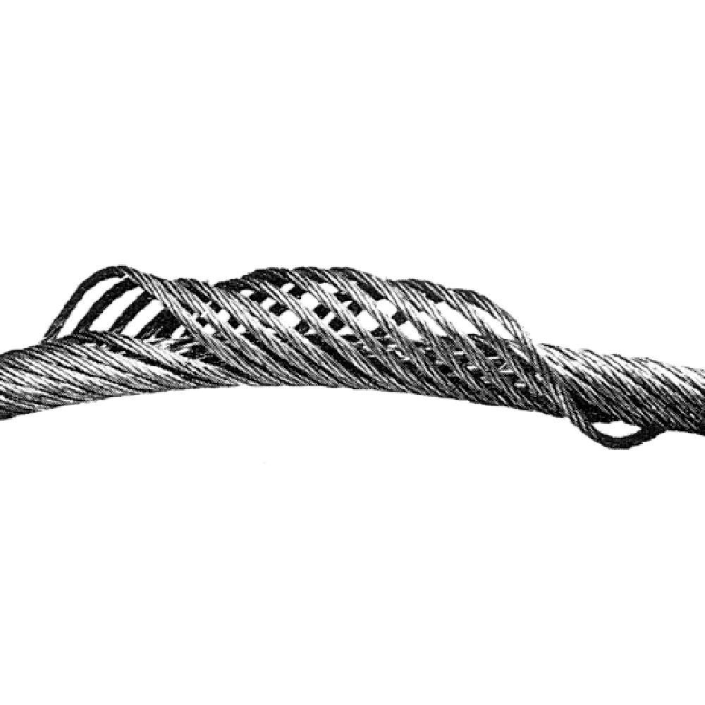
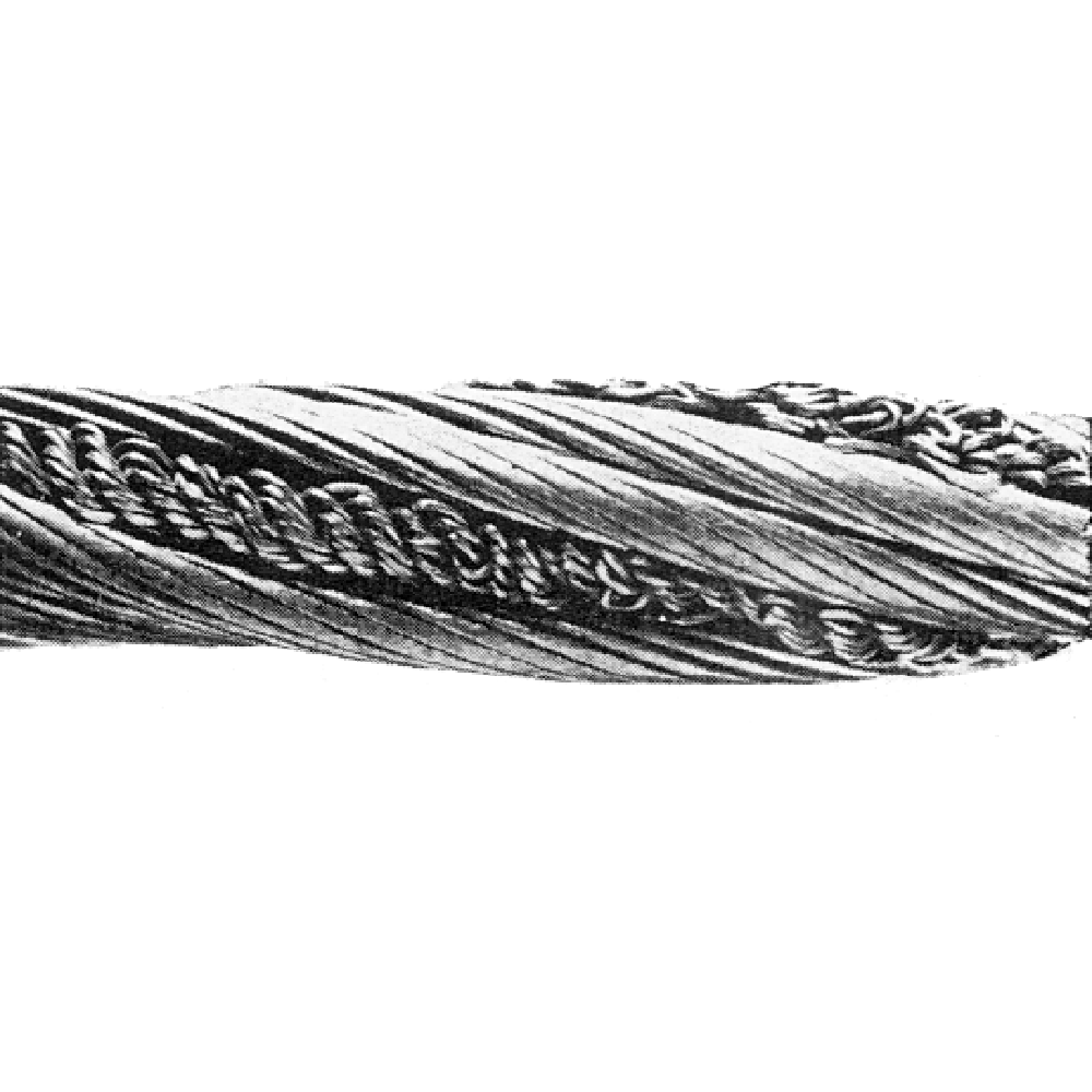
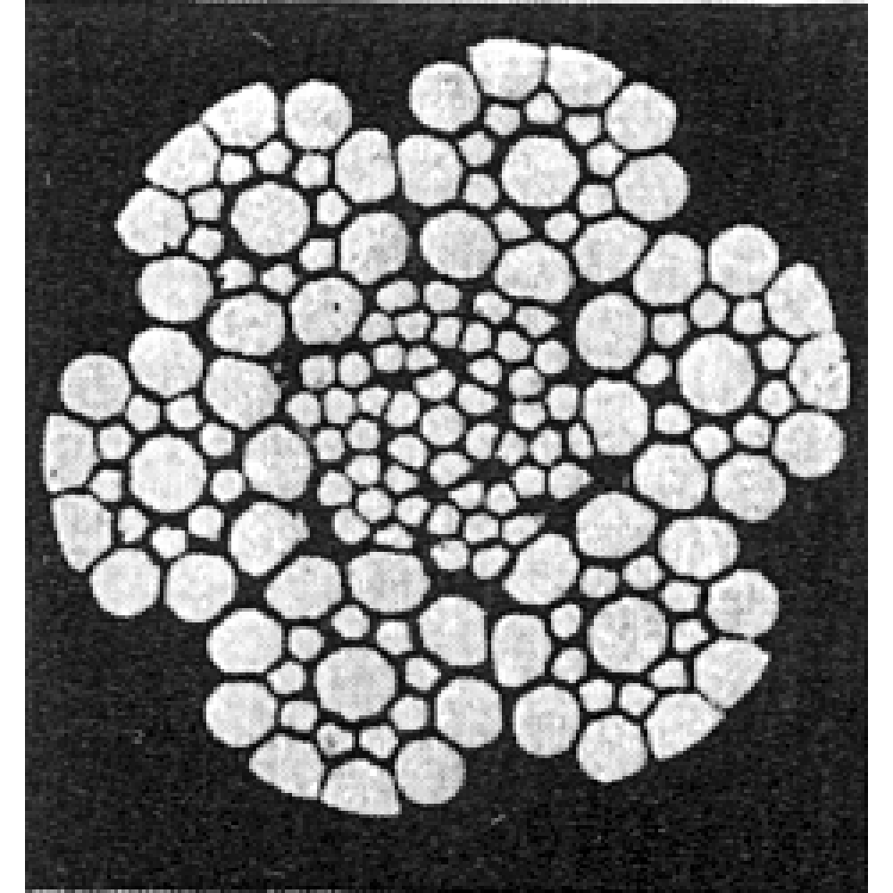
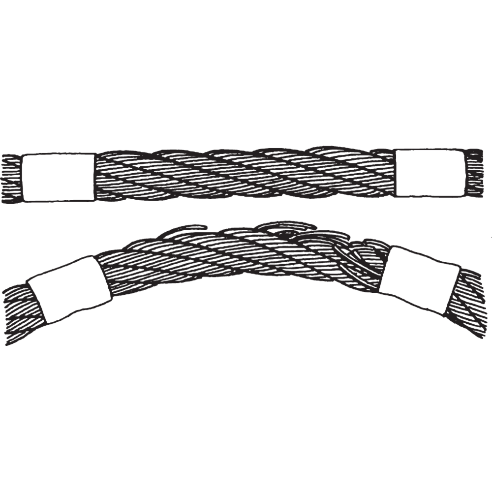
The pictures show typical examples of wire rope deterioration.
WARNING! Failure to take adequate precautions could result in injury.
|
Rope category number
|
Number of load-bearing wires in the outer layer of strands in the rope a
|
Number of visible brokenb outer wires over a length of:
|
|||||
|
Section of rope working in steel sheaves and/or spooling on a single-layer drum
|
Sections of rope spooling on a multi-layer drum c
|
||||||
|
Classed M1 to M4 or class unknown d
|
All classes
|
||||||
|
Ordinary lay
|
Lang lay
|
Ordinary and Lang lay
|
|||||
|
RCN
|
n
|
6de
|
30de
|
6de
|
30de
|
6de
|
30de
|
|
1
|
n ≤ 50
|
2
|
4
|
1
|
2
|
4
|
8
|
|
2
|
51 ≤ n ≤ 75
|
3
|
6
|
2
|
3
|
6
|
12
|
|
3
|
76 ≤ n ≤ 100
|
4
|
8
|
2
|
4
|
8
|
16
|
|
4
|
101 ≤ n ≤ 120
|
5
|
10
|
2
|
5
|
10
|
20
|
|
5
|
121 ≤ n ≤ 140
|
6
|
11
|
3
|
6
|
12
|
22
|
|
6
|
141 ≤ n ≤ 160
|
6
|
13
|
3
|
6
|
12
|
26
|
|
7
|
161 ≤ n ≤ 180
|
7
|
14
|
4
|
7
|
14
|
28
|
|
8
|
181 ≤ n ≤ 200
|
8
|
16
|
4
|
8
|
16
|
32
|
|
9
|
201 ≤ n ≤ 220
|
9
|
18
|
4
|
9
|
18
|
36
|
|
10
|
221 ≤ n ≤ 240
|
10
|
19
|
5
|
10
|
20
|
38
|
|
11
|
241 ≤ n ≤ 260
|
10
|
21
|
5
|
10
|
20
|
42
|
|
12
|
261 ≤ n ≤ 280
|
11
|
22
|
6
|
11
|
22
|
44
|
|
13
|
281 ≤ n ≤ 300
|
12
|
24
|
6
|
12
|
24
|
48
|
|
Ropes having outer strands of Seal construction where the number of wires in each strand is 19 or less (e.g. 6 x 19 Seal) are placed in this table two rows above that row in which the construction would normally be placed based on the number of load bearing wires in the outer layer of strands.
|
|||||||
|
a) Filler wires are not regarded as load-bearing wire and are not included in the values of n. |
|||||||
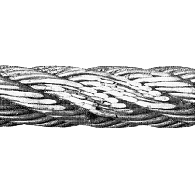
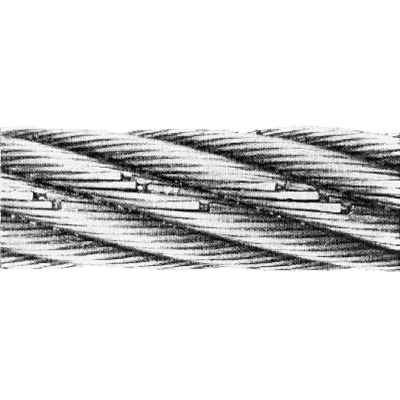
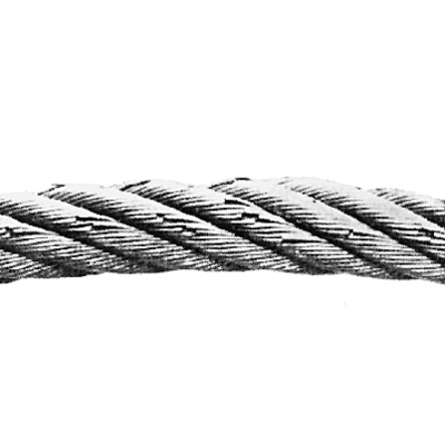
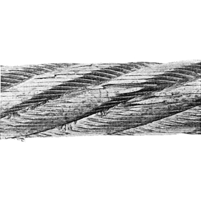
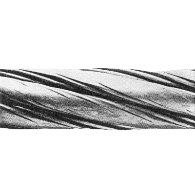
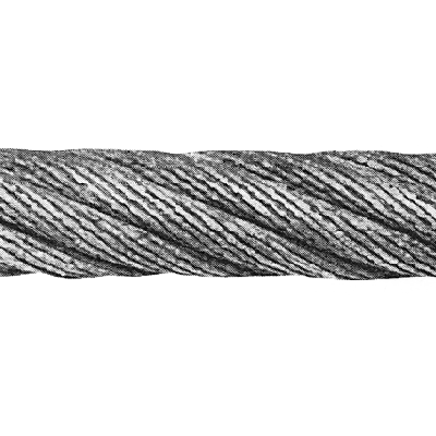
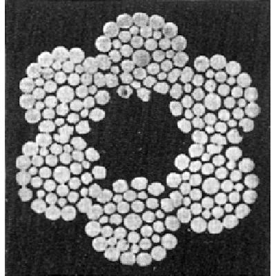
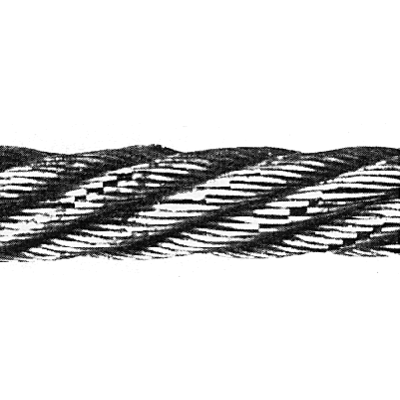
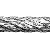
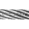
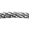
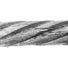


Examination
During examination of steel wire ropes attention should be made specifically to the parts of the rope that are, known from experience, to be exposed to wear and damage.
Wear, broken wires, distortion and corrosion are the most common visible signs of deterioration.
Wear is a normal feature of rope service and the correct rope construction ensures that it remains a secondary aspect of deterioration. Correct lubrication of the rope may help to reduce both outer and inner wear.
Broken wires are normal features of rope service towards the end of the rope's life, resulting from bending fatigue and wear. The local break up of wires may indicate some mechanical fault in the equipment. Correct lubrication in service will increase fatigue performance.
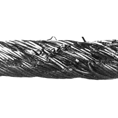
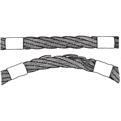
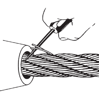
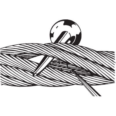
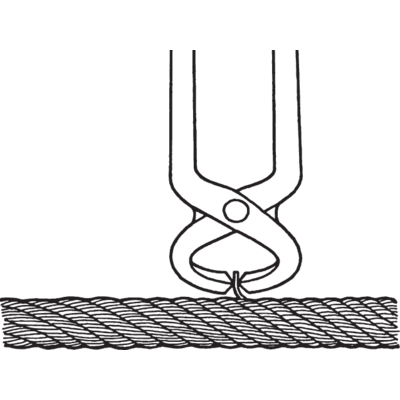
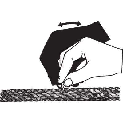
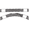
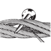
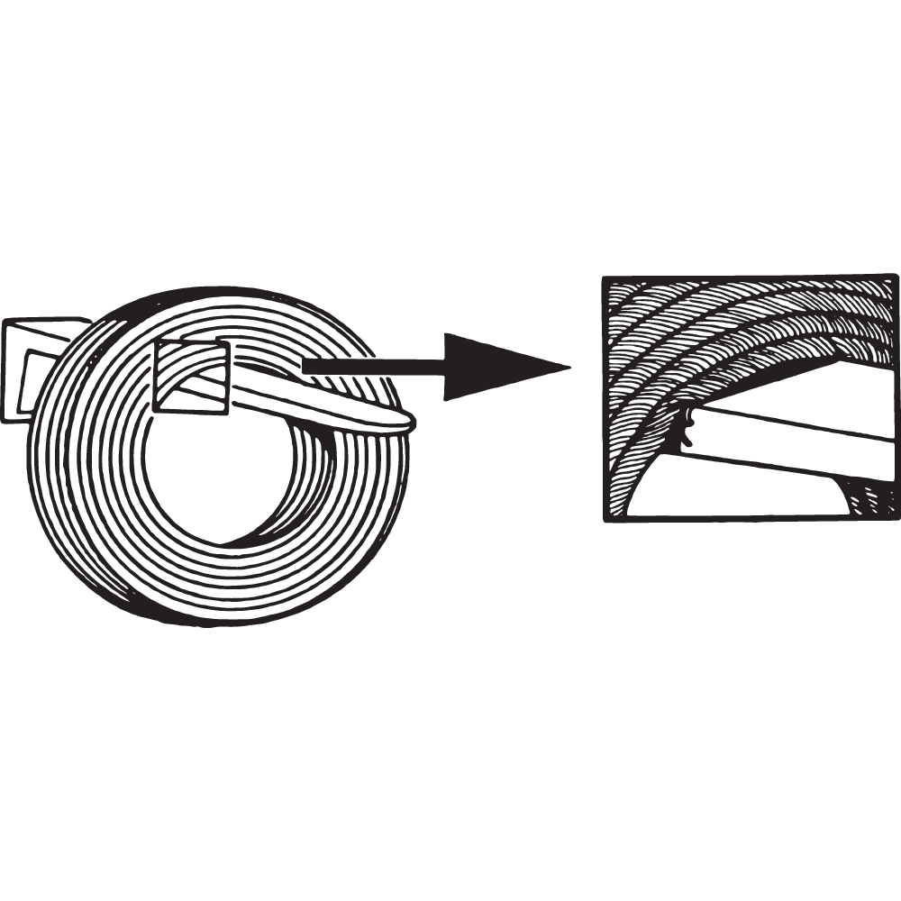
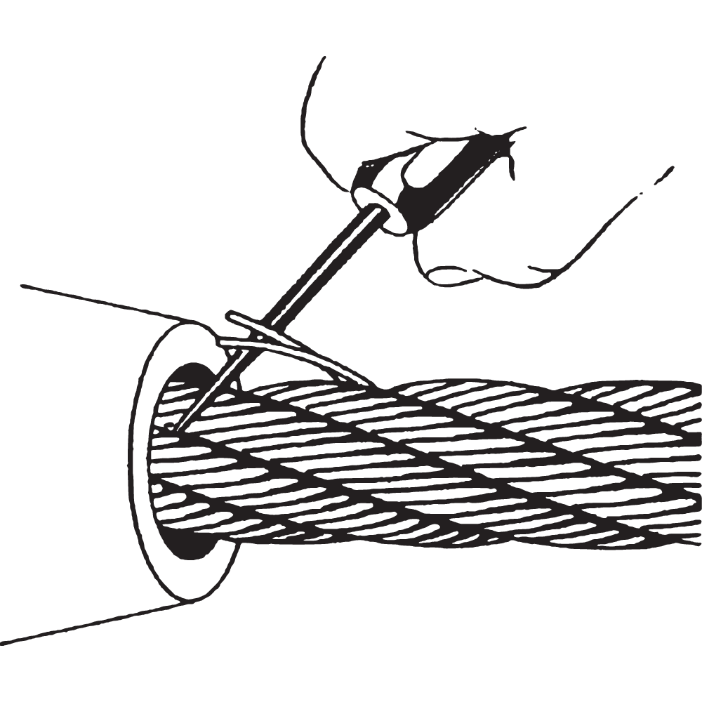
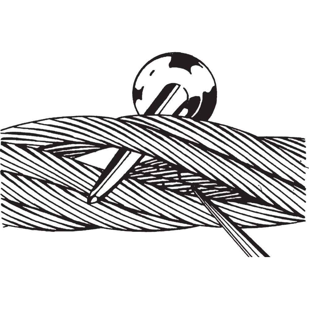
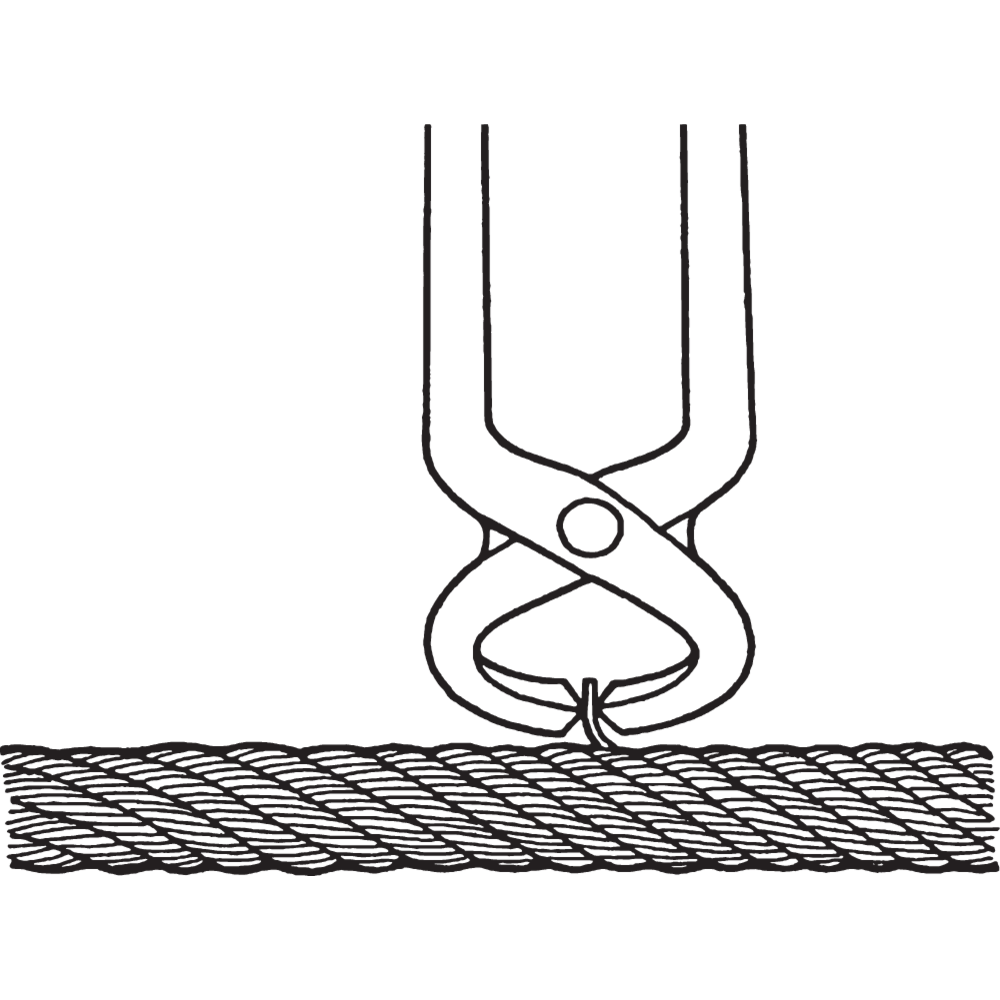
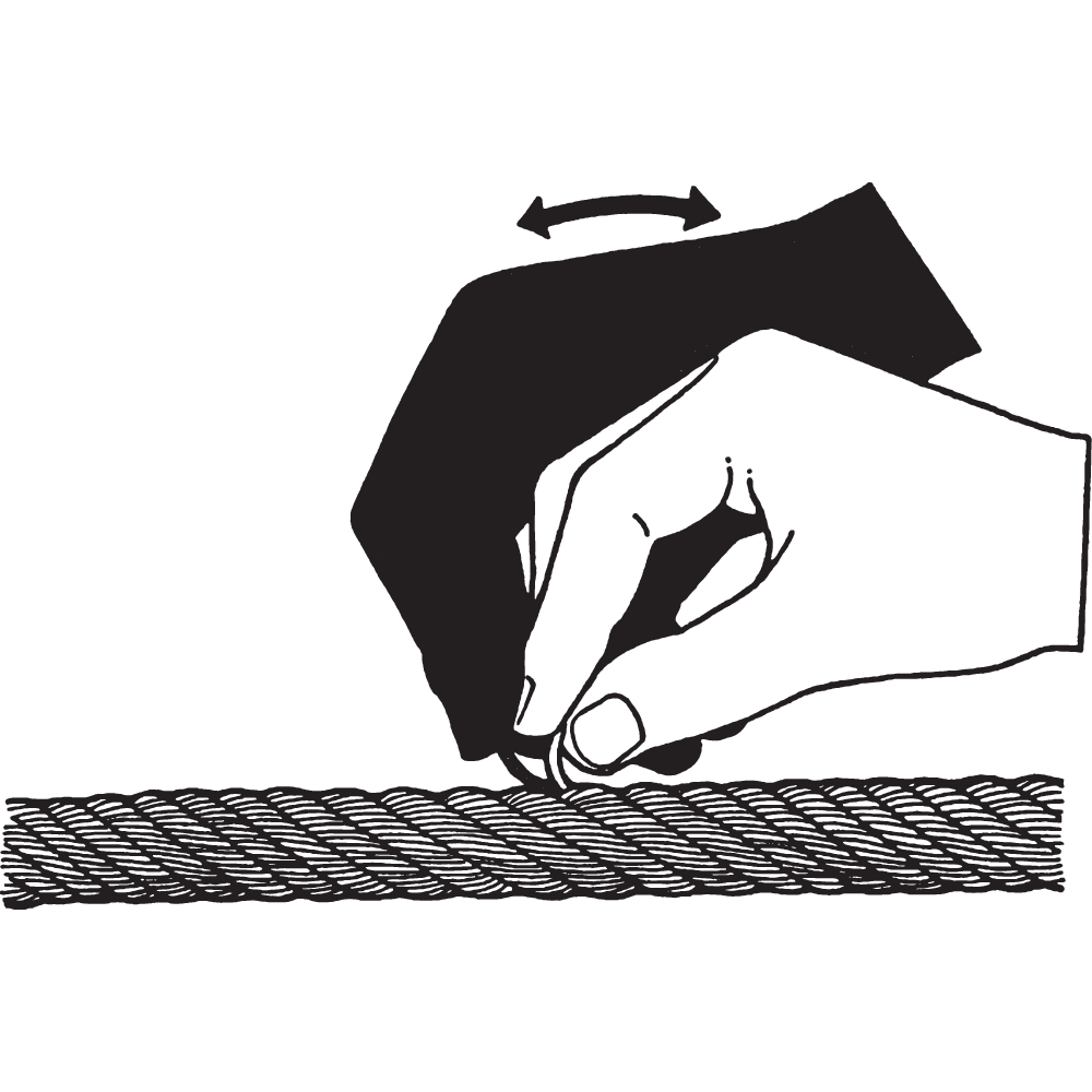
Individual broken wires shall be attended to by removing the wire, see figure.
Distortions are usually as a result of mechanical damage, and if severe, can considerably affect rope strength.
Corrosion, both outer and inner, indicate unsuitable grease. Pitting on the external wire surface can result in broken wires. Inner corrosion occurs in some environments when lubrication is inadequate or of a unsuitable type. A reduction in rope diameter will frequently indicate this condition, but confirmation can only be made by an internal examination of the rope.
WARNING! Do not cut the wire, bend it until it breaks close to the inside of the strajd. This reduces the risk of the ends of wires sticking out of the rope.



Maintenance
Steel wire ropes should get periodical service. The period depend on equipment and grade of use. Periodical maintenance can affect the lift of the rope prominently.
![lubrication-[Converted][new_225mm_2](/sites/certex-fi/techdoc_import/Technical%20information%20general/STEEL%20WIRE%20ROPE%20PRODUCTS/OLD_Technical%20information/Steel%20wire%20rope/Handling%20and%20installation/10493/image-thumb__10493__general-base/lubrication--converted-new_225mm_2.e3ea05f0.png)
![lubrication-[Converted][new_225mm_2](/sites/certex-fi/techdoc_import/Technical%20information%20general/STEEL%20WIRE%20ROPE%20PRODUCTS/OLD_Technical%20information/Steel%20wire%20rope/Handling%20and%20installation/10493/image-thumb__10493__general-thumb/lubrication--converted-new_225mm_2.13c1249f.png)
![lubrication-[Converted][new_225mm_2](/sites/certex-fi/techdoc_import/Technical%20information%20general/STEEL%20WIRE%20ROPE%20PRODUCTS/OLD_Technical%20information/Steel%20wire%20rope/Handling%20and%20installation/10493/image-thumb__10493__general-base/lubrication--converted-new_225mm_2.e3ea05f0.png)

Sheaves
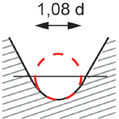
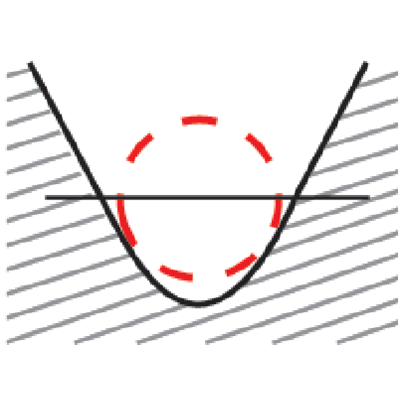
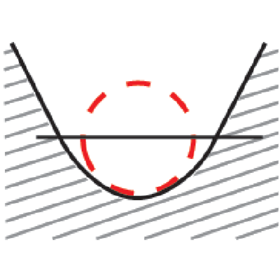
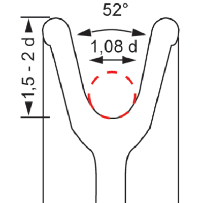
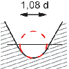
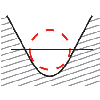
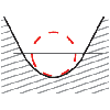
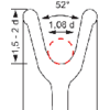
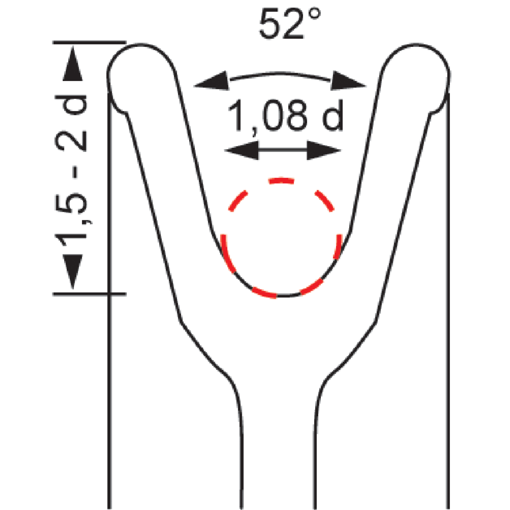
Before installing a new rope the sheave grooves, layers and lubrication should be checked.
Measure the groove diameter with a radius gauge and check the general condition of the groove.
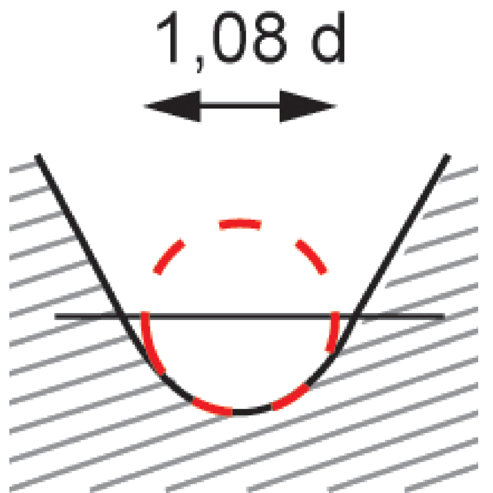
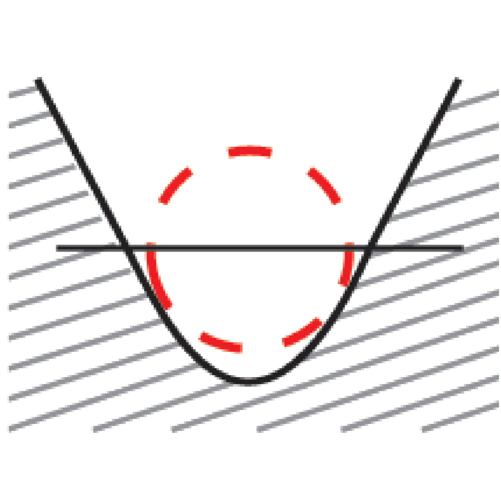
Groove diameter shall be nominal rope diameter +8% to +14% (0,54 x d to 0,57 x d).
WARNING! Worn sheaves should be replaced/refurbished.


Maintenance - Lubrication
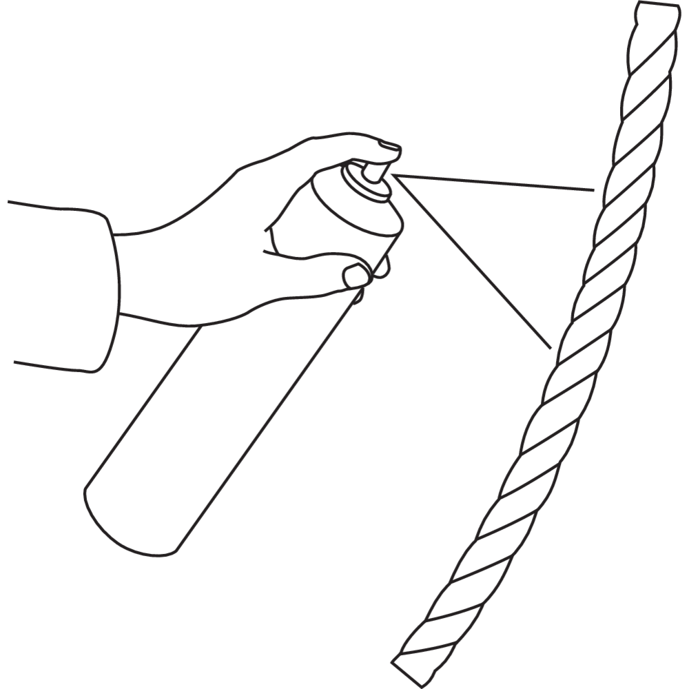
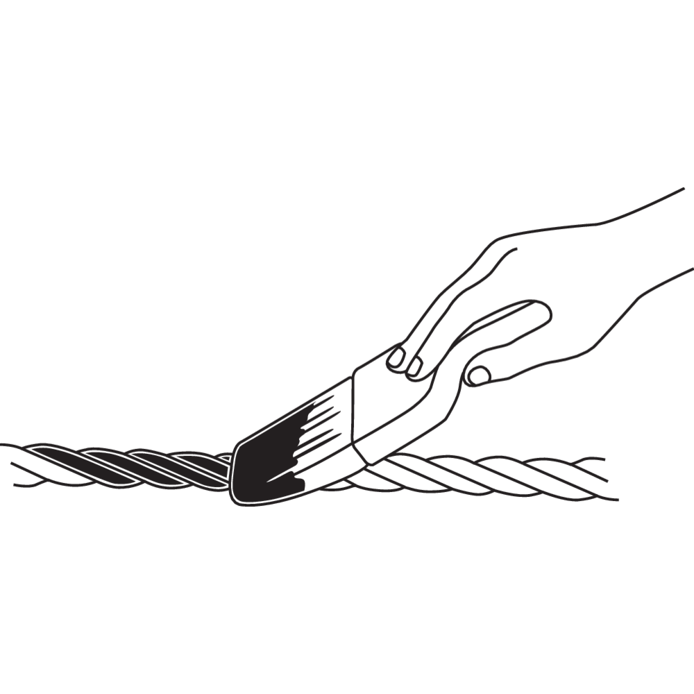
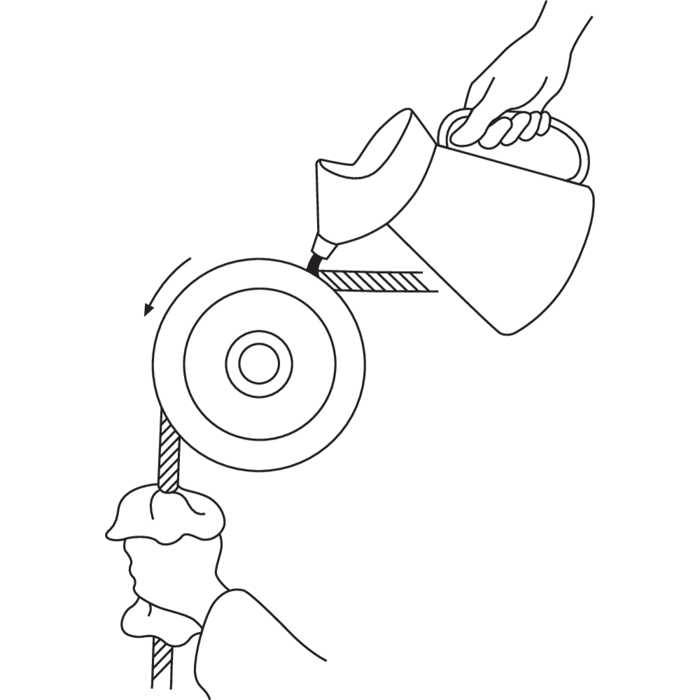
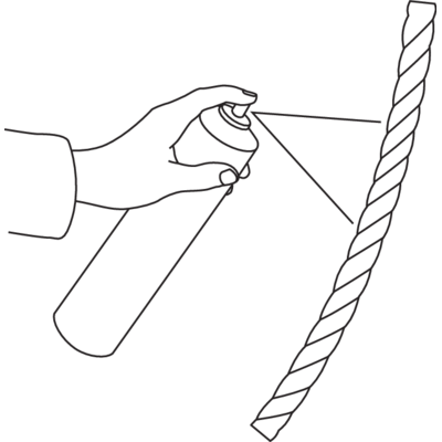
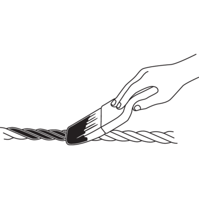
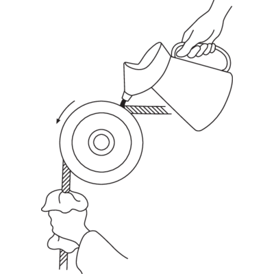
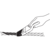
When a wire rope is in operation the individual wires rub against each other. To reduce the friction the rope is lubricated during manufacture. The lubrication improves the performance of the rope and increases its life.
Check the lubrication of the rope immediately after installation and clean the rope from inappropriate material, for example sand and dirt, periodically the rope should also be lubricated before use.
It is also important that lubrication is made in intervals of time depending on operating conditions and intensity of use.
WARNING! An unlubricated or incorrectly lubricated rope has a significantly reduced life.
Contact CERTEX for further advice and help on lubrication.
![diagram [Converted]_225mm_2](/sites/certex-fi/techdoc_import/Technical%20information%20general/STEEL%20WIRE%20ROPE%20PRODUCTS/Steel%20wire%20rope/Steel%20wire%20rope%20-%20handling%20and%20installation/10461/image-thumb__10461__general-base/diagram-converted-_225mm_2.7cebba5a.png)
![diagram [Converted]_225mm_2](/sites/certex-fi/techdoc_import/Technical%20information%20general/STEEL%20WIRE%20ROPE%20PRODUCTS/Steel%20wire%20rope/Steel%20wire%20rope%20-%20handling%20and%20installation/10461/image-thumb__10461__general-thumb/diagram-converted-_225mm_2.6c67cc4d.png)
![diagram [Converted]_225mm_2](/sites/certex-fi/techdoc_import/Technical%20information%20general/STEEL%20WIRE%20ROPE%20PRODUCTS/Steel%20wire%20rope/Steel%20wire%20rope%20-%20handling%20and%20installation/10461/image-thumb__10461__general-base/diagram-converted-_225mm_2.7cebba5a.png)


![drum [new2]_225mm_2](/sites/certex-fi/techdoc_import/Technical%20information%20general/STEEL%20WIRE%20ROPE%20PRODUCTS/OLD_Technical%20information/Steel%20wire%20rope/Handling%20and%20installation/10488/image-thumb__10488__product-large/drum-new2-_225mm_2.ed578800.png)
![eye-sock [Converted]_225mm_2](/sites/certex-fi/techdoc_import/Technical%20information%20general/STEEL%20WIRE%20ROPE%20PRODUCTS/OLD_Technical%20information/Steel%20wire%20rope/Handling%20and%20installation/10490/image-thumb__10490__product-large/eye-sock-converted-_225mm_2.0100647e.png)
![multiple-layers-[Converted][new]_225mm_2](/sites/certex-fi/techdoc_import/Technical%20information%20general/STEEL%20WIRE%20ROPE%20PRODUCTS/OLD_Technical%20information/Steel%20wire%20rope/Handling%20and%20installation/10489/image-thumb__10489__product-large/multiple-layers--converted-new-_225mm_2.fa1fad14.png)
![drum-capacity[new]_225mm_2](/sites/certex-fi/techdoc_import/Technical%20information%20general/STEEL%20WIRE%20ROPE%20PRODUCTS/OLD_Technical%20information/Steel%20wire%20rope/Handling%20and%20installation/10491/image-thumb__10491__product-large/drum-capacity-new-_225mm_2.b32633d6.png)
![fleetangle[new]._225mm_2](/sites/certex-fi/techdoc_import/Technical%20information%20general/STEEL%20WIRE%20ROPE%20PRODUCTS/Steel%20wire%20rope/Steel%20wire%20rope%20-%20handling%20and%20installation/10456/image-thumb__10456__product-large/seil_5.696f37f7.png)
![feather-weight[new]_225mm_2](/sites/certex-fi/techdoc_import/Technical%20information%20general/STEEL%20WIRE%20ROPE%20PRODUCTS/OLD_Technical%20information/Steel%20wire%20rope/Handling%20and%20installation/10492/image-thumb__10492__product-large/feather-weight-new-_225mm_2.70272117.png)
![lubrication-[Converted][new_225mm_2](/sites/certex-fi/techdoc_import/Technical%20information%20general/STEEL%20WIRE%20ROPE%20PRODUCTS/OLD_Technical%20information/Steel%20wire%20rope/Handling%20and%20installation/10493/image-thumb__10493__product-large/lubrication--converted-new_225mm_2.7f84ab5e.png)
![diagram [Converted]_225mm_2](/sites/certex-fi/techdoc_import/Technical%20information%20general/STEEL%20WIRE%20ROPE%20PRODUCTS/Steel%20wire%20rope/Steel%20wire%20rope%20-%20handling%20and%20installation/10461/image-thumb__10461__product-large/diagram-converted-_225mm_2.e7341c65.png)
